Tool parameters, 1 t o ol d a tabase – HEIDENHAIN CNC Pilot 4290 V7.1 User Manual
Page 614
614
8.1 T
o
ol D
a
tabase
Tool parameters
The use of the tool parameters is indicated by the following letters:
G: Basic data
S: Depicting the tool during simulation/control graphics
TP: Information for TURN PLUS (tool selection)
Parameters for turning tools
Example: Tool type 111
Parameters in dialog box 1
G
S
TP
ID: Tool ID number
•
•
•
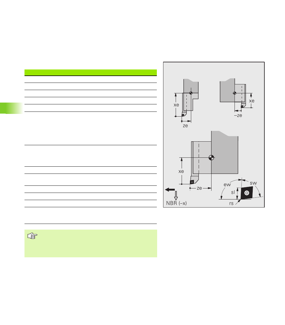
X, Z, Y dim. (xe, ze, ye): Setting dimensions
•
–
–
Tool an. (ew): Tool angle
•
•
•
Tip an. (sw): Point angle
•
•
•
Radius (rs): Cutting radius
•
•
•
Cut.wid. (sb)
Recessing tool: Cutting width
•
•
•
Threading tool: Distance between tooth edge
and tooth tip
•
•
–
Knurling tool: Roller width
–
•
–
Cut.lg. (sl)
Knurling tool: Roller diameter
–
•
–
Other tools: Cutting length
•
•
•
NBR: Secondary machining direction
•
–
•
X, Z, Y comp. (DX, DZ, DY): Compensation values
(maximum +/– 10 mm)
•
–
–
Dir.rot.: Direction of spindle rotation
•
–
•
Usab.lg.(nl): Usable length for internal tools
–
–
•
Dep.imm. (et): Maximum infeed depth
•
•
•
S comp. (DS): Special compensation of the third
side of the tool (maximum cutting width +/– 10
mm). See also G148 and G150/G151.
•
–
–
Threading tool:
“ze” and “xe” are measured from the tooth edge.
The direction of rotation defines whether an overhead
tool or a standard tool is used.