Contour dimensioning, 2 cont our simulation – HEIDENHAIN CNC Pilot 4290 V7.1 User Manual
Page 375
HEIDENHAIN CNC PILOT 4290
375
5.2 Cont
our Simulation
Contour dimensioning
Position the cursor:
For element or point dimensioning, position the cursor (small red
square) as follows:
U
Cursor left/right: Changes to the next contour point
U
Cursor up/down: Changes the contour (for example,
between blank and finished contour)
U
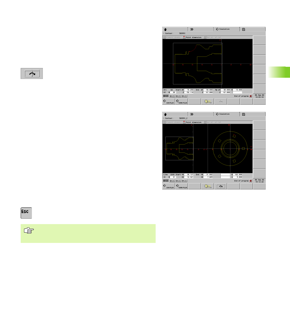
Changes to the next simulation window (prerequisite:
there are contours on the reference planes).
Element dimensioning
U
Select “Dimension. > Element dimension.”
U
Position the cursor on a contour element: The simulation shows the
data of the marked contour element. The arrow shows the direction
of the contour description.
Point dimensioning:
U
Select “Dimension. > Point dimension.”
Set reference point:
U
Position the cursor to the reference point
U
Select “Set reference point”
Measure the contour point:
U
Position the cursor to the contour point to be measured: the
simulation shows the dimensions of the contour point with respect
to the reference point and the selected reference plane (XC, XY,
etc.).
Cancel the reference point:
U
Select “reference point off”: The simulation deletes the reference
point.
Back to the contour simulation:
U
ESC key
You can also call the dimensioning functions in the
Machining/Motion mode of simulation (“Dimensioning”
menu item).