5 low-speed infrared trans, 1 subcarrier generation, 2 transmit baseband modu – Maxim Integrated MAXQ Family User Manual
Page 98: 1 subcarrier generation using timer 2 low -20, 2 transmit baseband modulator -20, Maxq family user’s guide, 1 subcarrier generation using timer 2 low, 2 transmit baseband modulator
9-20
MAXQ Family User’s Guide
9.5 Low-Speed Infrared Transmit/Receive Support Using Timer 2
The MAXQ microcontroller can provide hardware to simplify support for low-speed infrared (IR) communication. To take advantage of
the embedded hardware, the microcontroller device must be equipped with at least one Timer 2 module; that Timer must have at least
two pins implemented and that Timer must be configured to a specific mode of operation.
The associated Timer 2 has to be configured into the dual 8-bit mode of operation. More specifically, it should be configured to the 8-
bit Counter + 8-bit Timer/PWM mode. The T2OE[0] bit should be configured to logic 0 if it is intended that the T2 pin serve in the IRRX
capacity. The T2OE[1] control bit should be configured to logic 0 if it is intended to serve in the IRTX capacity, since the internal IR
hardware provides a separate control mechanism for enabling the carrier output to the T2PB pin. The 8-bit Timer/PWM is used to cre-
ate the appropriate subcarrier waveform, while the 8-bit counter is used for modulation of the subcarrier when transmitting and for com-
pare timing when decoding the IR receive waveforms. It is expected that the IR receive waveform will be coming directly from an exter-
nal IR receiver module or circuitry, which can provide a filtered digital output indicating carrier presence by a logic 0 or logic 1.
9.5.1 Subcarrier Generation Using Timer 2 Low
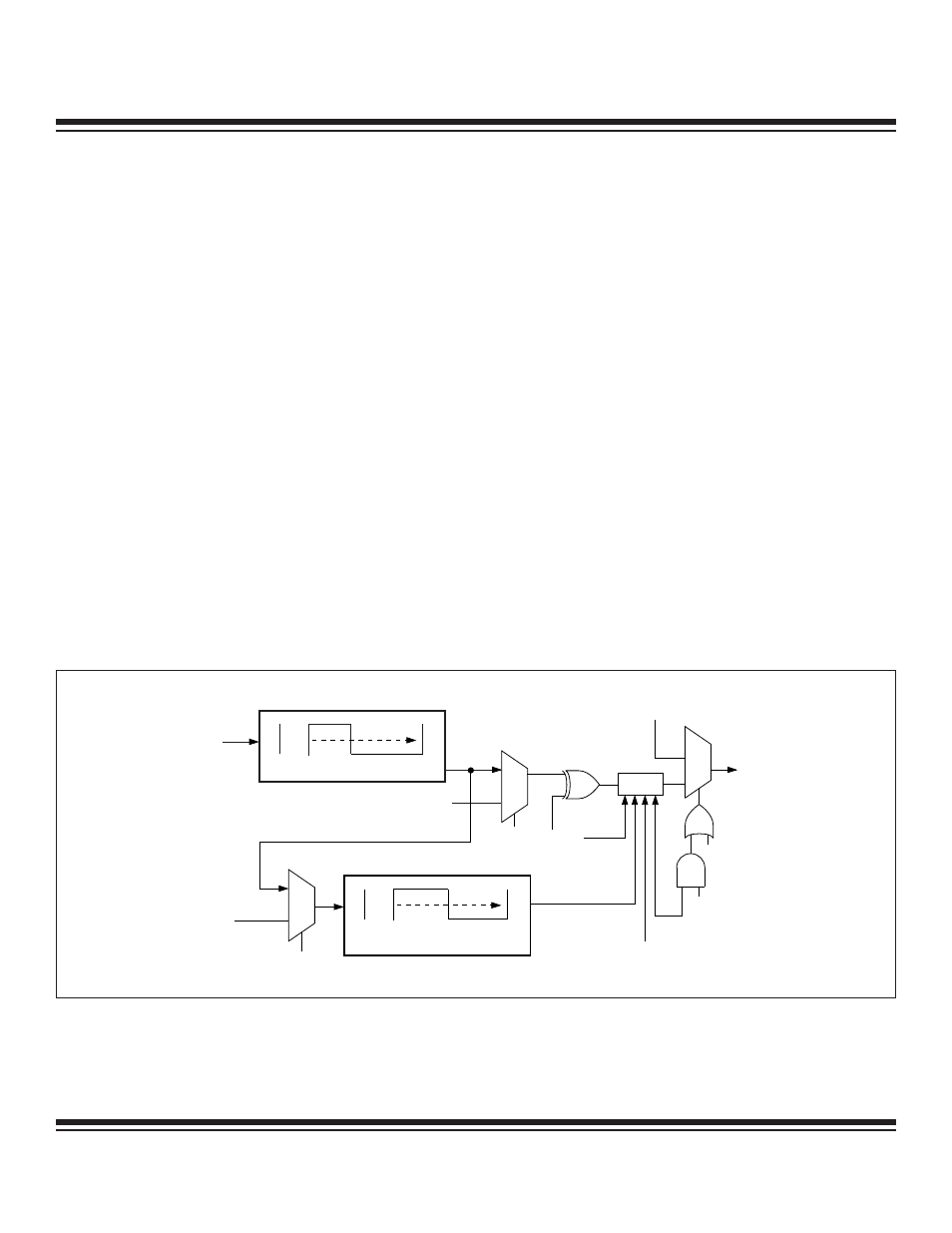
Generation of the subcarrier frequency will always be performed by the 8-bit Timer/PWM (T2L). The period and duty cycle for the sub-
carrier is determined by the settings of reload and compare registers as described in the Timer 2 documentation. Figure 9-9 diagrams
the basic subcarrier generation and its path to the T2PB/IRTX output pin. Notice that the T2POL[1] bit control still applies.
9.5.2 Transmit Baseband Modulator
Generation of the baseband modulator waveform is handled by the 8-bit counter (T2H). Normally, the 8-bit counter sources the exter-
nal T2A pin signal and counts edges as defined by CCF[1:0]. However, when the IR hardware is enabled (IREN = 1), this counter
sources the output of the T2L subcarrier waveform. This allows user software to define the number of subcarrier cycles through the
T2RH register, which should be counted before T2H overflow. The T2POL[1] bit defines the starting (idle) state for the T2L output and
the edge that are counted by the T2H counter. If T2POL[1] = 1, the T2L output idles high and only rising edges are counted by T2H.
If T2POL[1] = 0, the T2L output idles low and only falling edges are counted by T2H. A separate register bit, IR bit-bang (IRBB), is
used to determine whether the T2L output is gated or output to the pin for the next X subcarrier cycles. The value of X, as alluded to
earlier, can be controlled by modifying the reload value. When IRBB = 1 and IRTX = 1, the T2L output is enabled onto the T2PB/IRTX
pin. When IRBB = 0 and IRTX = 1, the gated (idle) condition, as defined by T2POL[1], is in effect on the pin.
00h
T2CL
T2RL
FFh
T2CLK
T2POL[1]
T2MD = 1
T2OE[1] = 0
POx.x DATA
(IF PDx.x = 1)
T2PB
PIN
T2L 8-BIT TIMER
T2H 8-BIT COUNTER
T2P PIN
GATE
IREN
IRBB
(SOFTWARE CONTROL)
1
0
1
0
IRTX = 1
IREN = 1
00h
FFh
T2RH
T2RH
FFh
T2RH
Figure 9-9. IR Transmit Subcarrier Generation and Baseband Modulator Control
Maxim Integrated