1 timer 0, 1 timer 0 mode: 13-bit t, 1 timer 0 -2 – Maxim Integrated MAXQ Family User Manual
Page 67: 1 timer 0 mode: 13-bit timer/counter -2, Table 7-1. timer 0 mode summary -2, Maxq family user’s guide, Table 7-1. timer 0 mode summary
7-2
MAXQ Family User’s Guide
SECTION 7: TIMER/COUNTER 0 MODULE
The Timer/Counter 0 Module allows the MAXQ to control a 16-bit programmable timer/counter. Whether and how many Timer/Counter
0 Modules are implemented in a given MAXQ-based microcontroller is product dependent.
7.1 Timer 0
Timer 0 is the first type of 16-bit timer/counter. Timer 0 consists of a 16-bit register in two bytes, T0H and T0L. Timer 0 is enabled by
the Timer 0 Run Control (TR0) bit in the T0CN register. Timer 0 supports four basic modes of operations. The mode of operation is con-
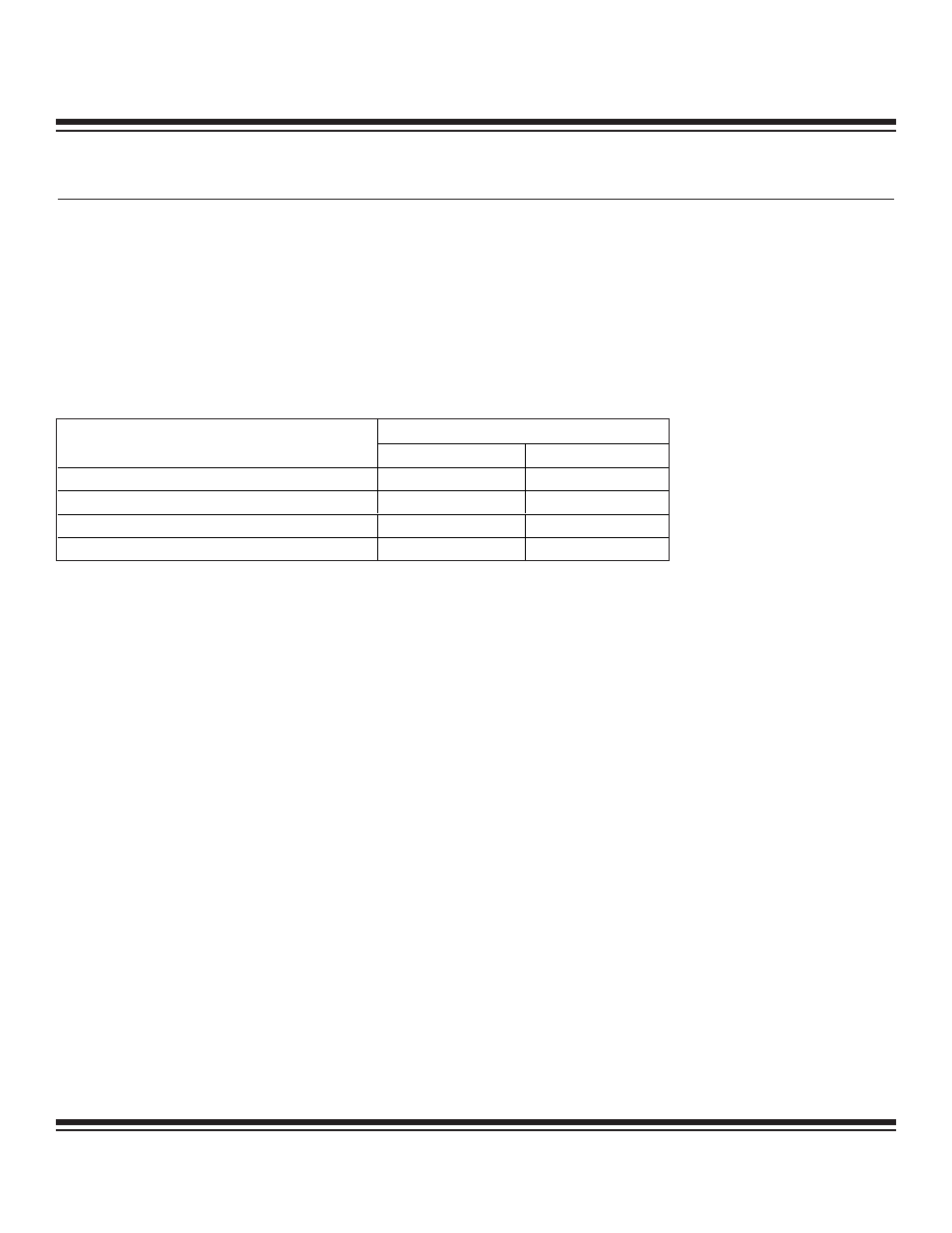
trolled by the Timer 0 Control (T0CN) register. Table 7-1 shows these four modes and the corresponding T0CN register bit settings.
Each of the four Timer 0 operational modes can optionally select that an external pin serve as the Timer 0 input clock, and can also
gate the input clock source (either internal or external) based upon an external pin state. The gating feature is useful in measuring the
pulse width of external signals.
Table 7-1. Timer 0 Mode Summary
7.1.1 Timer 0 Mode: 13-Bit Timer/Counter
As referenced in Table 7-1, setting T0CN register bits M1:M0 = 00b selects the 13-bit Timer/Counter operating mode for Timer 0. T0H
provides the 8 MSbs (most significant bits) of the 13-bit timer, while bits 4–0 of T0L serve as the 5 LSbs (least significant bits) of the
13-bit timer. Bit 4 of T0L is used as a ripple-out to T0H bit 0, thereby completely bypassing bits 5 to 7 of T0L. The upper three bits of
T0L are indeterminate. When the 13-bit count reaches 1FFFh (all ones), the next count causes it to roll over to 0000h. The TF0 (T0CN.5)
flag is set, and an interrupt occurs if enabled.
Once the timer is started using the TR0 (T0CN.4) timer enable, the timer counts as long as one of the following conditions is true:
1) GATE (T0CN.3) = 0
2) GATE (T0CN.3) = 1 and T0G (external pin) = 1
The Timer 0 input clock is normally a function of the system clock frequency as defined by the T0M (T0CN.6) bit. However, an exter-
nal signal at the T0 pin can serve as the input clock if the C/T (T0CN.2) bit is set to 1. When using the T0 pin as an input clock,
Timer/Counter 0 counts 1-to-0 transitions on the pin. To reliably detect external 1-to-0 transitions, the input signal high and low times
each must be a minimum of one system clock in duration.
Note that when the Timer 0 input clock is derived from the system clock, changing the system clock divide ratio (via the CKCN regis-
ter bit controls) consequently changes the input clock to the Timer.
Note 1: When C/T = 1, the counter configuration is in effect, and the T0 pin signal provides the input clock.
Note 2: When GATE = 1, the gating control is in effect, and the T0G = 0 pin state causes gating of the Timer/Counter input clock.
T0CN REGISTER BIT SETTINGS
TIMER 0 OPERATIONAL MODE
M1
M0
13-Bit Timer/Counter
0
0
16-Bit Timer/Counter
0
1
8-Bit Timer/Counter with Auto-Reload
1
0
Two 8-Bit Timer/Counters
1
1
Maxim Integrated