1 i/o port: type a, 2 i/o port: type b, 1 i/o port: type a -2 – Maxim Integrated MAXQ Family User Manual
Page 59: 2 i/o port: type b -2, Figure 6-1. type a port pin schematic -2, Figure 6-2. type b port pin schematic -2, Maxq family user’s guide
6-2
MAXQ Family User’s Guide
SECTION 6: GENERAL-PURPOSE I/O MODULE
The General-Purpose I/O Module (GPIO) for the MAXQ supports multiple 8-bit port types, each having different I/O characteristics.
From a software perspective, each port appears as a group of Peripheral Registers with unique addresses. The exact quantity and
type of ports provided by the GPIO Module is product-dependent. Each of the four different types of I/O ports are described.
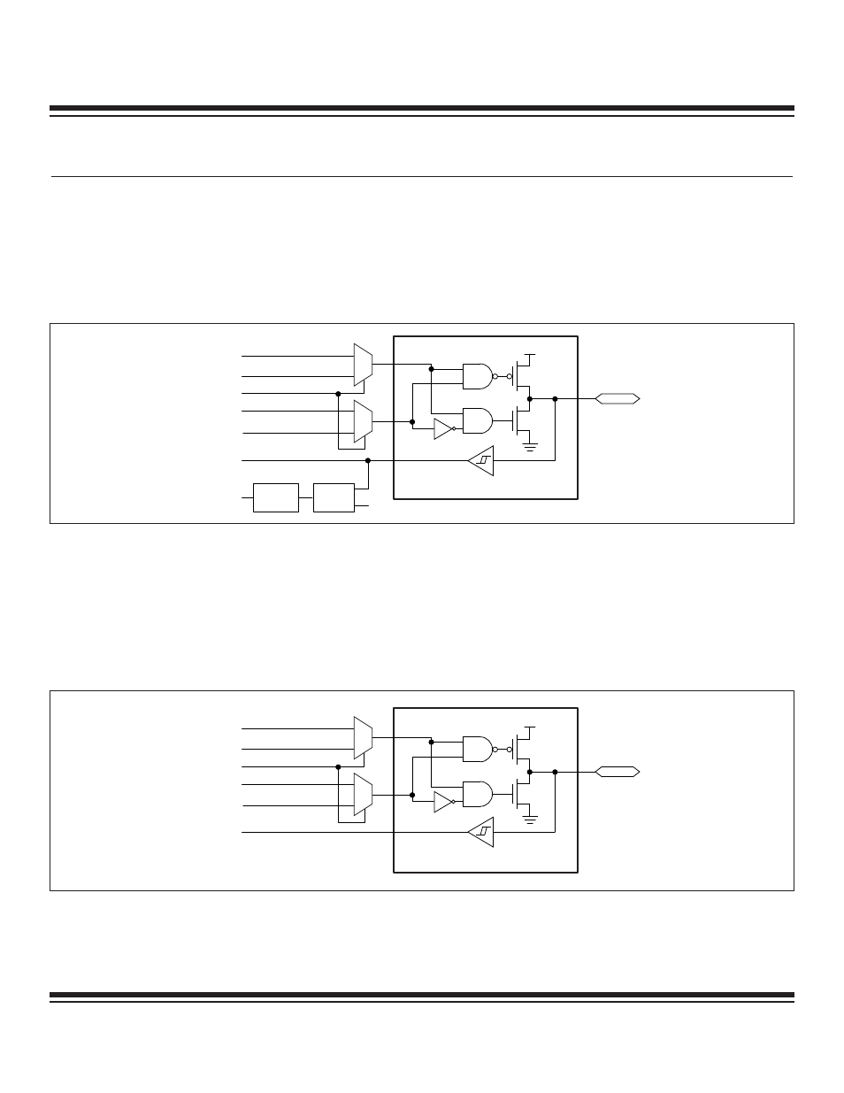
6.1 I/O Port: Type A
The Type A port can be used as a bidirectional I/O port. A port consists of eight general-purpose input/output pins and all the registers
needed to control and configure them. Each pin is independently controllable. Up to six pins of each type A port can be configured as
external interrupts. Each interrupt function is supported by its own interrupt flag, and each can be independently enabled.
6.2 I/O Port: Type B
The Type B port can also be used as a bidirectional I/O port. The Type B port consists of eight general-purpose input/output pins and
three registers needed to control and configure them. Each pin is independently controllable. Type B port pins are intended to support
secondary special functions. The special functions associated with these port pins are generally implemented in peripheral modules
to the MAXQ CPU, which can be enabled, controlled, and monitored using dedicated Peripheral Registers.
Enabling the special function automatically converts the pin to that function. The I/O drive characteristics for these pins are the same
no matter whether the pin is configured for general-purpose I/O or whether it is being used for the special function.
PIN.x
PD.x
SF ENABLE
PO.x
PI.x OR SF INPUT
SF OUTPUT
SF DIRECTION
FLAG
IT0/IT1
Vdd
I/O PAD
MUX
MUX
DETECT
CIRCUIT
INTERRUPT
FLAG
MAXQ
Figure 6-1. Type A Port Pin Schematic
PIN.x
PD.x
SF ENABLE
PO.x
PI.x OR SF INPUT
SF OUTPUT
SF DIRECTION
Vdd
I/O PAD
MUX
MUX
MAXQ
Figure 6-2. Type B Port Pin Schematic
Maxim Integrated