2 timer 1 mode: 16-bit e, 2 timer 1 mode: 16-bit event capture -3, Maxq family user’s guide – Maxim Integrated MAXQ Family User Manual
Page 74: 2 timer 1 mode: 16-bit event capture
If the C/T1 bit (T1CN.1) is logic 0, the timer’s input clock is a function of the system clock. When C/T1 = 1, pulses on the T1 pin are
counted. Counting or timing is enabled or disabled using the with the Timer 1 Run Control bit = TR1 (T1CN.2). This mode, including
the optional reload control, is illustrated in Figure 8-1.
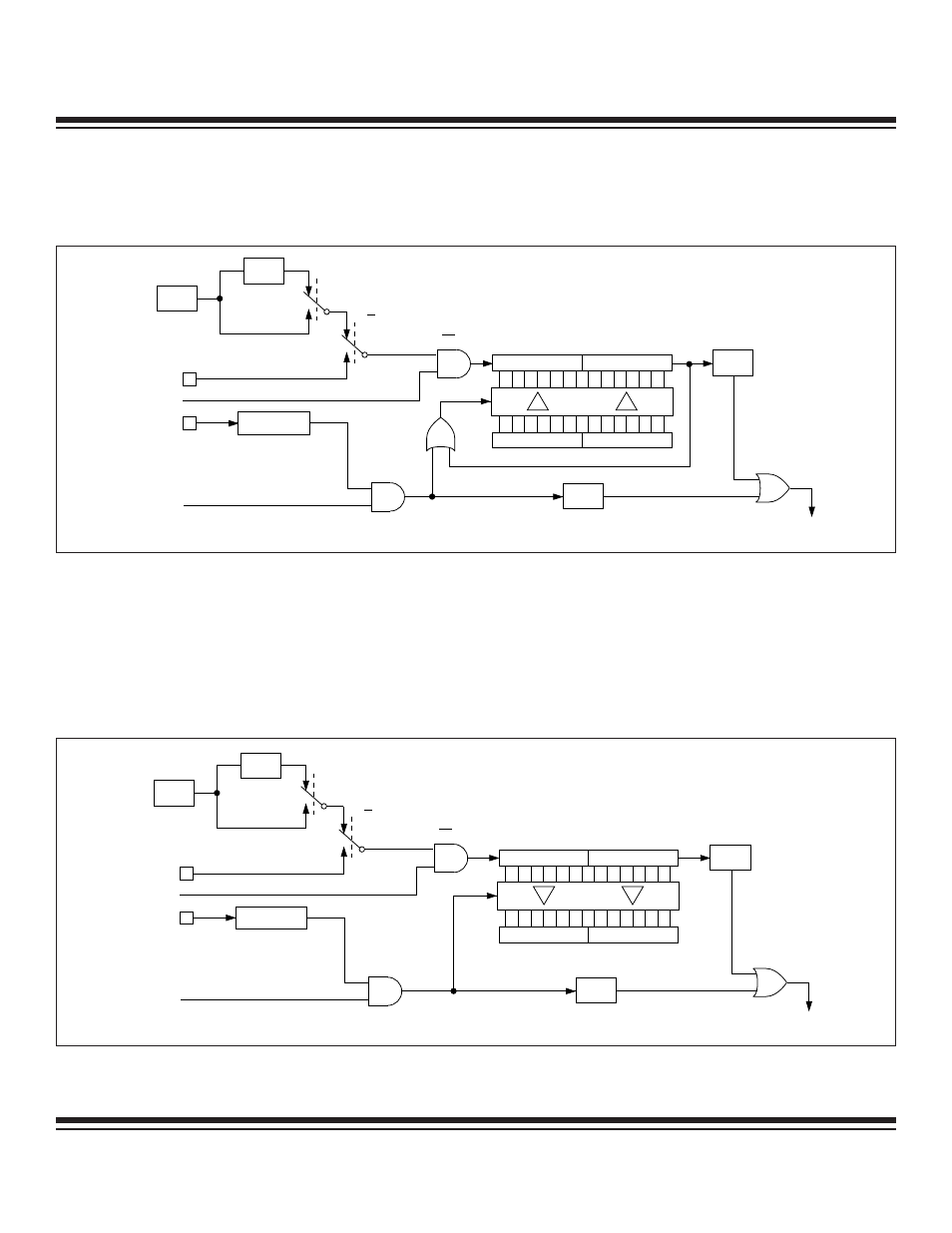
8.1.2 Timer 1 Mode: 16-Bit Event Capture
The 16-bit capture mode is invoked by setting the CP/RL1 (T1CN.0) bit to logic 1. Timer 1 begins counting from the value supplied in
T1H and T1L until reaching an overflow state, i.e., rolls over from FFFFh to 0000, at which point it sets the TF1 Flag. This flag can gen-
erate an interrupt if enabled. The optional capture function is enabled by setting the EXEN1 (T1CN.3) bit to logic 1. Once this has been
done, a 1-to-0 transition on the T1EX pin causes the value in Timer 1 (T1H, T1L) to be transferred into the capture registers (T1CH,
T1CL) and the EXF1 (T1CN.6) flag to be set. Setting of the EXF1 flag can generate an interrupt if enabled. If the EXEN1 bit is set to
logic 0, 1-to-0 transitions on the T1EX pin do not automatically trigger a capture event.
8-3
MAXQ Family User’s Guide
TR1 = T1CN.2
CLK
0
0
1
1
0
0
7 8
7 8
15
15
C/T1 = T1CN.1
T1M = T1MD.0
EXEN1 = T1CN.3
T1 PIN
T1EX PIN
DIVIDE
BY 12
TF1 =
T1CN.7
TIMER 1
INTERRUPT
SYSTEM
CLOCK
ƒ
T1L
T1H
T1CL
T1CH
EXF1 =
T1CN.6
Figure 8-1. Timer/Counter 1 16-Bit Auto-Reload Mode
TR1 = T1CN.2
CLK
CAPTURE
0
0
C/T1 = T1CN.1
T1M = T1MD.0
EXEN1 = T1CN.3
T1 PIN
T1EX PIN
DIVIDE
BY 12
TF1 =
T1CN.7
TIMER 1
INTERRUPT
SYSTEM
CLOCK
ƒ
T1L
T1H
EXF1 =
T1CN.6
1
1
0
0
7 8
7 8
15
15
T1CL
T1CH
Figure 8-2. Timer/Counter 1 16-Bit Event Capture
Maxim Integrated