1 timer 1, 1 timer 1 mode: 16-bit t, 1 timer 1 -2 – Maxim Integrated MAXQ Family User Manual
Page 73: Table 8-1. timer/counter 1 mode summary -2, Maxq family user’s guide, Table 8-1. timer/counter 1 mode summary
8-2
MAXQ Family User’s Guide
SECTION 8: TIMER/COUNTER 1 MODULE
The Timer/Counter 1 Module allows the MAXQ to control a 16-bit programmable timer/counter. Whether and how many Timer/Counter
1 Modules are implemented in a given MAXQ-based microcontroller is product dependent.
8.1 Timer 1
Timer 1 is the second type of 16-bit timer/counter. Timer 1 consists of a 16-bit register in two bytes, T1H and T1L. Timer 1 is enabled
by the Timer 1 Run Control (TR1) bit in the T1CN register. Unlike Timer 0, Timer 1 is operable only as a full 16-bit timer/counter. However,
it supports many optional modes not available on Timer 0. These optional modes are enabled by T1CN register bits. To support the
extended functionality of Timer 1, a 16-bit capture register composed of the T1CH, T1CL bytes and a second mode control register
(T1MD) are implemented. Table 8-1 shows the Timer 1 operational modes and the corresponding T1CN register bit settings. With
exception of the Timer 1 clock output mode, all Timer 1 modes can optionally select that an external pin serve as the Timer 1 input
clock.
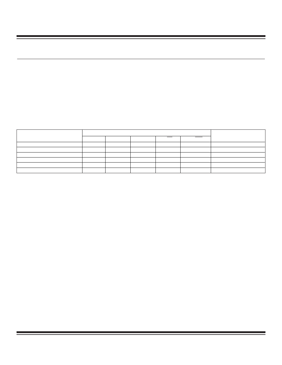
Table 8-1. Timer/Counter 1 Mode Summary
8.1.1 Timer 1 Mode: 16-Bit Timer/Counter with Auto-Reload
The Timer 1 auto-reload mode is configured by setting the CP/RL1 (T1CN.0) bit to logic 0. In this mode, Timer 1 performs a simple
timer or counter function where it behaves similarly to the 16-bit timer/counter mode offered on Timer 0, but adds a separate 16-bit
reload value and the ability to trigger a reload with an external pin.
Timer 1 begins counting from the value supplied in T1H and T1L. When Timer 1 reaches an overflow state, i.e., rolls over from FFFFh
to 0000, it sets the TF1 Flag. This flag can generate an interrupt if enabled. In addition, the timer restores its starting value and begins
timing (or counting) again. The starting value is preloaded by software into the capture registers T1CH and T1CL. These registers can-
not be used for capture functions while also performing auto-reload, so these modes are mutually exclusive.
When in auto-reload mode, Timer 1 can also be forced to reload with the T1EX pin. If EXEN1 (T1CN.3) is set to logic 1, then a 1-to-0
transition on T1EX causes a reload. Otherwise, the T1EX pin is ignored.
T1CN REGISTER BIT SETTINGS
TIMER 1 OPERATIONAL MODE
T1OE
DCEN
EXEN1
C/T1
CP/RL1
OPTIONAL CONTROL
Auto-Reload
0
0
0
x
0
—
Auto-Reload Using T1EX Pin
0
0
1
x
0
—
Capture Using T1EX Pin
0
0
1
x
1
—
Up/Down Count Using T1EX Pin
0
1
0
x
0
—
—
0
x
x
1
x
Input clock = T1 pin
Clock Output on T1 Pin
1
x
x
0
0
—
Maxim Integrated