4 timer/counter 2 peripher, 1 timer/counter 2 config, 4 timer/counter 2 peripheral registers -15 – Maxim Integrated MAXQ Family User Manual
Page 93: Maxq family user’s guide, 4 timer/counter 2 peripheral registers, 1 timer/counter 2 configuration register (t2cfg)
9-15
MAXQ Family User’s Guide
9.4 Timer/Counter 2 Peripheral Registers
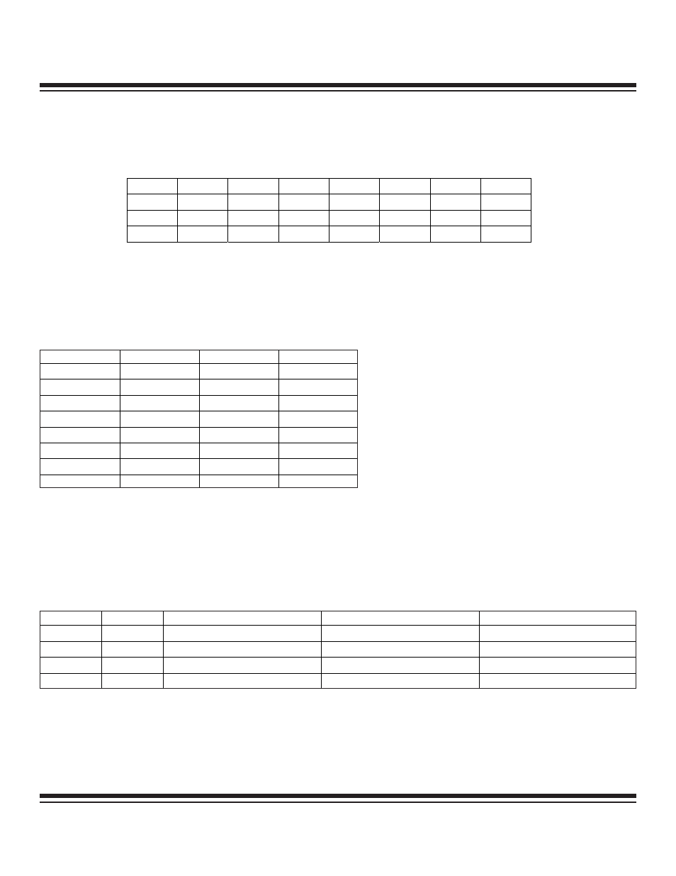
9.4.1 Timer/Counter 2 Configuration Register (T2CFG)
Bit 7: Timer 2 Clock Input Select Bit (T2CI). Setting this bit enables an alternate input clock source to the Timer 2 block. The alter-
nate input clock selection is the 32kHz clock. The alternate input clock must be sampled by the system clock, which requires that the
system clock be at least 4 x 32kHz for proper operation unless the system clock is also source from the 32kHz crystal.
Bits 6 to 4: Timer 2 Clock Divide 2:0 Bits (T2DIV[2:0]). These three bits select the divide ratio for the timer clock-input clock (as a
function of the system clock) when operating in timer mode with T2CI = 0.
Bit 3: Timer 2 Mode Select (T2MD). This bit enables the dual 8-bit mode of operation. The default-reset state is 0, which selects the
16-bit mode of operation. When the dual 8-bit mode is established, the primary timer/counter (T2H) carries all of the counter/capture
functionality while the secondary 8-bit timer (T2L) must operate in timer compare mode, sourcing the defined internal clock.
0 = 16-bit mode (default)
1 = dual 8-bit mode
Bits 2 to 1: Capture/Compare Function Select Bits (CCF[1:0]). These bits, in conjunction with the C/T2 bit, select the basic operat-
ing mode of Timer 2. In the dual 8-bit mode of operation (T2MD = 1), the T2L timer only operates in compare mode.
Bit 0: Counter/Timer Select (C/
T2). This bit enables/disables the edge counter mode of operation for the 16-bit counter (T2H:T2L) or
the 8-bit counter (T2H) when the dual 8-bit mode of operation is enabled (T2MD = 1). The edge for counting (rising/falling/both) is
defined by the CCF[1:0] bits.
0 = timer mode
1 = counter mode
Bit #
7
6
5
4
3
2
1
0
Name
T2CI
T2DIV2
T2DIV1
T2DIV0
T2MD
CCF1
CCF0
C/T2
Reset
0
0
0
0
0
0
0
0
Access
rw
rw
rw
rw
rw
rw
rw
rw
r = read, w = write
T2DIV2
T2DIV1
T2DIV0
DIVIDE RATIO
0
0
0
1
0
0
1
2
0
1
0
4
0
1
1
8
1
0
0
16
1
0
1
32
1
1
0
64
1
1
1
128
CCF1
CCF0
EDGE(S)
C/T2 = 0 (TIMER MODE)
C/T2 = 1 (COUNTER MODE)
0
0
None
Compare Mode
Disabled
0
1
Rising
Capture/Reload
Counter
1
0
Falling
Capture/Reload
Counter
0
1
Rising and Falling
Capture/Reload
Counter
Maxim Integrated