3 ir-scan sequence, 3 ir-scan sequence -3, Figure 15-1. tap controller state diagram -3 – Maxim Integrated MAXQ Family User Manual
Page 154: Maxq family user’s guide
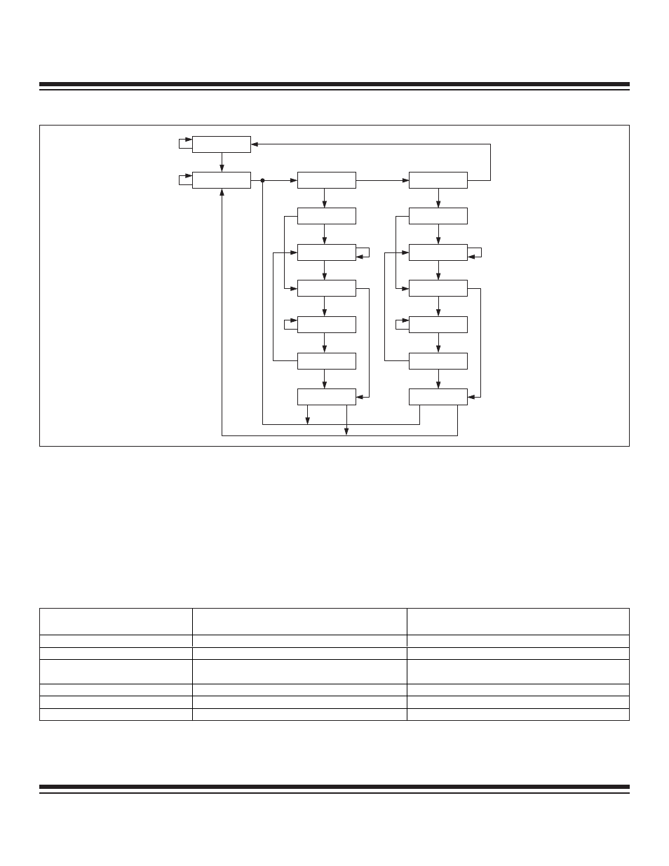
15.2.3 IR-Scan Sequence
The controller state sequence allows instructions (e.g., 'Debug' and 'System Programming') to be shifted into the instruction register
starting from the Select-IR-Scan state. In the TAP, the instruction register is connected between the TDI input and the TDO output.
Inside the IR-Scan Sequence, the Capture-IR state loads a fixed binary pattern (001b) into the 3-bit shift register and the Shift-IR state
causes shifting of TDI data into the shift register and serial output to TDO, least significant bit first. Once the desired instruction is in
the shift register, the instruction can be latched into the parallel instruction register (IR2:0) on the falling edge of TCK in the Update-IR
state. The contents of the 3-bit instruction shift register and parallel instruction register (IR2:0) are summarized with respect to the TAP
controller states in Table 15-1.
Table 15-1. Instruction Register Content vs. TAP Controller State
15-3
MAXQ Family User’s Guide
TEST-LOGIC-RESET
RUN-TEST-IDLE
SELECT-DR-SCAN
EXIT2-DR
CAPTURE-DR
SHIFT-DR
EXIT1-DR
PAUSE-DR
UPDATE-DR
SELECT-IR-SCAN
EXIT2-IR
CAPTURE-IR
SHIFT-IR
EXIT1-IR
PAUSE-IR
UPDATE-IR
1
0
1
1
1
1
1
1
1
1
1
1
1
1
1
0
0
0
0
0
0
0
0
0
0
0
0
0
1
1
0
0
Figure 15-1. TAP Controller State Diagram
TAP CONTROLLER STATE
INSTRUCTION SHIFT REGISTER
PARALLEL (3-BIT) INSTRUCTION REGISTER (IR2:0)
Test-Logic-Reset
Undefined
Set to By-pass (011b) Instruction
Capture-IR
Load 001b at the rising edge of TCK
Retain last state
Shift-IR
Input data via TDI and Shift towards TDO at the rising
edge of TCK
Retain last state
Exit1-IR, Exit2-IR, Pause-IR
Retain last state
Retain last state
Update-IR
Retain last state
Load from shift register at the falling edge of TCK
All other states
Undefined
Retain last state
Maxim Integrated