7 (type d) external inte, Maxq family user’s guide, 7 (type d) external interrupt flag register (eifx) – Maxim Integrated MAXQ Family User Manual
Page 64
Bit 3: Enable External Interrupt 3 (EX3)
0 = external interrupt 3 function disabled
1 = external interrupt 3 function enabled
Bit 2: Enable External Interrupt 2 (EX2)
0 = external interrupt 2 function disabled
1 = external interrupt 2 function enabled
Bit 1: Enable External Interrupt 1 (EX1)
0 = external interrupt 1 function disabled
1 = external interrupt 1 function enabled
Bit 0: Enable External Interrupt 0 (EX0)
0 = external interrupt 0 function disabled
1 = external interrupt 0 function enabled
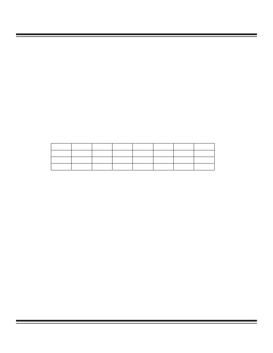
6.5.7 (Type D) External Interrupt Flag Register (EIFx)
Bit 7: External Interrupt 7 Flag (IE7). This flag is set when a negative edge (IT7 = 1) or a positive edge (IT7 = 0) is detected on the
INT7 pin. This bit remains set until cleared in software. Setting this bit by software causes an interrupt if enabled.
Bit 6: External Interrupt 6 Flag (IE6). This flag is set when a negative edge (IT6 = 1) or a positive edge (IT6 = 0) is detected on the
INT6 pin. This bit remains set until cleared in software. Setting this bit by software causes an interrupt if enabled.
Bit 5: External Interrupt 5 Flag (IE5). This flag will be set when a negative edge (IT5 = 1) or a positive edge (IT5 = 0) is detected on
the INT5 pin. This bit will remain set until cleared in software. Setting this bit by software causes an interrupt if enabled.
Bit 4: External Interrupt 4 Flag (IE4). This flag is set when a negative edge (IT4 = 1) or a positive edge (IT4 = 0) is detected on the
INT4 pin. This bit remains set until cleared in software. Setting this bit by software causes an interrupt if enabled.
Bit 3: External Interrupt 3 Flag (IE3). This flag is set when a negative edge (IT3 = 1) or a positive edge (IT3 = 0) is detected on the
INT3 pin. This bit remains set until cleared in software. Setting this bit by software causes an interrupt if enabled.
Bit 2: External Interrupt 2 Flag (IE2). This flag is set when a negative edge (IT2 = 1) or a positive edge (IT2 = 0) is detected on the
INT2 pin. This bit remains set until cleared in software. Setting this bit by software causes an interrupt if enabled.
Bit 1: External Interrupt 1 Flag (IE1). This flag is set when a negative edge (IT1 = 1) or a positive edge (IT1 = 0) is detected on the
INT1 pin. This bit remains set until cleared in software. Setting this bit by software causes an interrupt if enabled.
Bit 0: External Interrupt 0 Flag (IE0). This flag is set when a negative edge (IT0 = 1) or a positive edge (IT0 = 0) is detected on the
INT0 pin. This bit remains set until cleared in software. Setting this bit by software causes an interrupt if enabled.
6-7
MAXQ Family User’s Guide
Bit #
7
6
5
4
3
2
1
0
Name
IE7
IE6
IE5
IE4
IE3
IE2
IE1
IE0
Reset
0
0
0
0
0
0
0
0
Access
rw
rw
rw
rw
rw
rw
rw
rw
r = read, w = write
Maxim Integrated