3 communication via tap, 1 tap communication exa, 3 communication via tap -5 – Maxim Integrated MAXQ Family User Manual
Page 156: Figure 15-2. tap and tap controller -5, Maxq family user’s guide, 1 tap communication examples—ir-scan and dr-scan
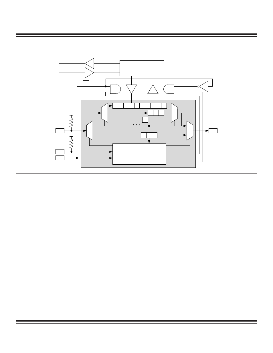
15.3 Communication via TAP
The TAP controller is in Test-Logic-Reset state after a power-on-reset. During this initial state, the instruction register contains By-pass
instruction and the serial path defined between the TDI and TDO pins for the Shift-DR state is the 1-bit bypass register. All TAP signals
(TCK, TMS, TDI, and TDO) default to being weakly pulled high internally on any reset. The TAP controller remains in the Test-Logic-
Reset state as long as TMS is held high. The TCK and TMS signals can be manipulated by the host to transition to other TAP states.
The TAP controller remains in a given state whenever TCK is held low.
For the host to establish a specific data communication link, a private instruction must be loaded into the IR2:0 register. Once the instruc-
tion is latched in the instruction parallel buffer at the Update-IR state, it is recognized by the TAP controller and the communication chan-
nel is established. In-Circuit Debug or In-System Programming commands and data can be exchanged between the host and the MAXQ
microcontroller by operating in the data register portion of the state sequence (i.e., DR-Scan). The TAP retains the private instruction that
was loaded into IR2:0 until a new instruction is shifted in or until the TAP controller returns to the Test-Logic-Reset state.
15.3.1 TAP Communication Examples—IR-Scan and DR-Scan
Figures 15-3 and 15-4 illustrate examples of communication between the host JTAG controller and the Test Access Port (TAP) of the
MAXQ microcontroller. The host controls the TCK and TMS signals to move through the desired TAP states while accessing the select-
ed shift register through the TDI input and TDO output pair.
15-5
MAXQ Family User’s Guide
TDO
TDI
WRITE
TCK
DEBUG
UPDATE-DR
UPDATE-DR
V
DD
TAP CONTROLLER
TMS
SYSTEM PROGRAM
READ
POWER-ON
RESET
BY-PASS
INSTRUCTION REGISTER
7
6
5
4
3
2
1
0
s1
s0
2
1
0
2
1
0
V
DD
Figure 15-2. TAP and TAP Controller
Maxim Integrated