Revision history, Maxq family user’s guide – Maxim Integrated MAXQ Family User Manual
Page 216
MAXQ Family User’s Guide
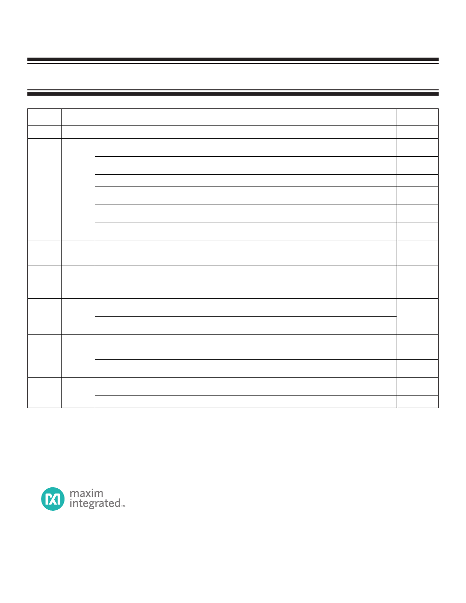
REVISION HISTORY
REVISION
NUMBER
REVISION
DATE
DESCRIPTION
PAGES
CHANGED
0
9/04
Original release.
—
Updated Loading a 16-bit register with a 16-bit immediate value:
Changed …PFX[2]…to…PFX[0].
28
Updated I/O Port: Type B:
Changed alternate function to special function.
54
Replaced Table 10.
62
Updated Timer 0 Mode: 16-Bit Timer/Counter:
Removed also from An interrupt also occurs if enabled…
63
Updated RTC Trim (RTRM) Register, (TRM4:0) Trim Calibration Bits:
Changed 32 seconds to 16 seconds
134
1
1/05
Updated JUMP NE:
Changed E = 1, branch taken to E = 0, branch taken.
165
2
4/05
Updated Debug Mode Special Considerations:
Added two bullets regarding single stepping because the debug engine step mechanism (that forces the IP to
8010h) does not allow a memory read from the utility ROM to work properly when single stepping.
149
3
9/05
Updated Polarity Control and Output Enable, Polarity Control:
Added the following sentence: When generating PWM output, please note that changing the compare match
register can result in a perceived duty cycle inversion if a compare match is missed or multiple compare
matches occur during the reload to overflow counting.
73, 75
Updated External Reset:
Added watchdog to list of causes for a reset condition.
4
10/05
Updated Watchdog Timer Reset:
Added and holds the
RST pin low to statement for a watchdog resetting the processor.
25
Updated Accessing the Multiplier:
Added and the OF bit to last sentence of first paragraph to clarify that the CLD bit, when set, clears all data
registers and the OF bit to zero.
111
5
2/06
Updated Hardware Multiplier Control (MCNT) Register Description, Bits CLD and OF:
Updated bit descriptions to clarify that the OF bit is cleared to 0 when the CLD bit is set to 1.
112
Created newer template-style document.
Updated layout for peripheral registers based on new template style.
All
6
9/08
Added Figure 9-14: Bit Length Decoding Example (omitted in error.)
9-23
Maxim Integrated 160 Rio Robles, San Jose, CA 95134 USA 1-408-601-1000
Maxim cannot assume responsibility for use of any circuitry other than circuitry entirely embodied in a Maxim product. No circuit patent licenses are implied.
Maxim reserves the right to change the circuitry and specifications without notice at any time. The parametric values (min and max limits) shown in the Electrical
Characteristics table are guaranteed. Other parametric values quoted in this data sheet are provided for guidance.
©
Maxim Integrated
The Maxim logo and Maxim Integrated are trademarks of Maxim Integrated Products, Inc.