10 (maxq10) accumulator n, 11 (maxq20) accumulator n, 12 prefix register (pfx[n – Maxim Integrated MAXQ Family User Manual
Page 53: 13 instruction pointer reg, 12 prefix register (pfx[n], bh[n]) -7, 13 instruction pointer register (ip, ch[0h]) -7, Maxq family user’s guide, 12 prefix register (pfx[n], bh[n]), 13 instruction pointer register (ip, ch[0h])
4-7
MAXQ Family User’s Guide
4.10 (MAXQ10) Accumulator n Register (A[n], 9h[nh])
Initialization: This register is cleared to 00h on all forms of reset.
Access: Unrestricted direct read/write access.
4.11 (MAXQ20) Accumulator n Register (A[n], 9h[nh])
Initialization: This register is cleared to 0000h on all forms of reset.
Access: Unrestricted direct read/write access.
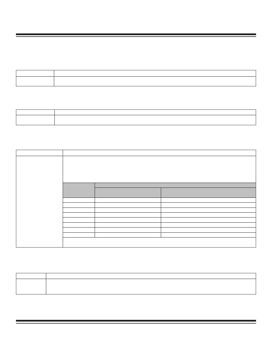
4.12 Prefix Register (PFX[n], Bh[n])
Initialization: This register is cleared to 0000h on all forms of reset.
Access: Unrestricted direct read/write access.
4.13 Instruction Pointer Register (IP, Ch[0h])
Initialization: This register is cleared to 8000h on all forms of reset.
Access: Unrestricted direct read/write access.
BIT
FUNCTION
A[n].7 to A[n].0
This register acts as the accumulator for all ALU arithmetic and logical operations when selected by the accumulator pointer
(AP). It can also be used as a general-purpose working register.
BIT
FUNCTION
IP.15 to IP.0
This register contains the address of the next instruction to be executed and is automatically incremented by 1 after each program
fetch. Writing an address value to this register will cause program flow to jump to that address. Reading from this register will not
affect program flow
.
BIT
FUNCTION
A[n].15 to A[n].0
This register acts as the accumulator for all ALU arithmetic and logical operations when selected by the accumulator pointer
(AP). It can also be used as a general-purpose working register.
BIT
FUNCTION
The Prefix register provides a means of supplying an additional 8 bits of high-order data for use by the succeeding
instruction as well as providing additional indexing capabilities. This register will only hold any data written to it for one
execution cycle, after which it will revert to 0000h. Although this is a 16-bit register, only the lower 8 bits are actually
used for prefixing purposes by the next instruction. Writing to or reading from any index in the Prefix module will select
the same 16-bit register. However, when the Prefix register is written, the index n used for the PFX[n] write also
determines the high-order bits for the register source and destination specified in the following instruction.
SOURCE, DESTINATION INDEX SELECTION
WRITE TO
SOURCE REGISTER
RANGE
DESTINATION REGISTER RANGE
PFX[0]
0h to Fh
0h to 7h
PFX[1]
10h to 1Fh
0h to 7h
PFX[2]
0h to Fh
8h to Fh
PFX[3]
10h to 1Fh
8h to Fh
PFX[4]
0h to Fh
10h to 17h
PFX[5]
10h to 1Fh
10h to 17h
PFX[6]
0h to Fh
18h to 1Fh
PFX[7]
10h to 1Fh
18h to 1Fh
PFX[n].15 to PFX[n].0
The index selection reverts to 0 (default mode allowing selection of registers 0h to 7h for destinations) after one cycle in
the same manner as the contents of the Prefix register.
Maxim Integrated