7 rtc sub-second alarm, 8 rtc trim register (rtrm), 7 rtc sub-second alarm register (rssa) -10 – Maxim Integrated MAXQ Family User Manual
Page 151: 8 rtc trim register (rtrm) -10, Maxq family user’s guide, 7 rtc sub-second alarm register (rssa)
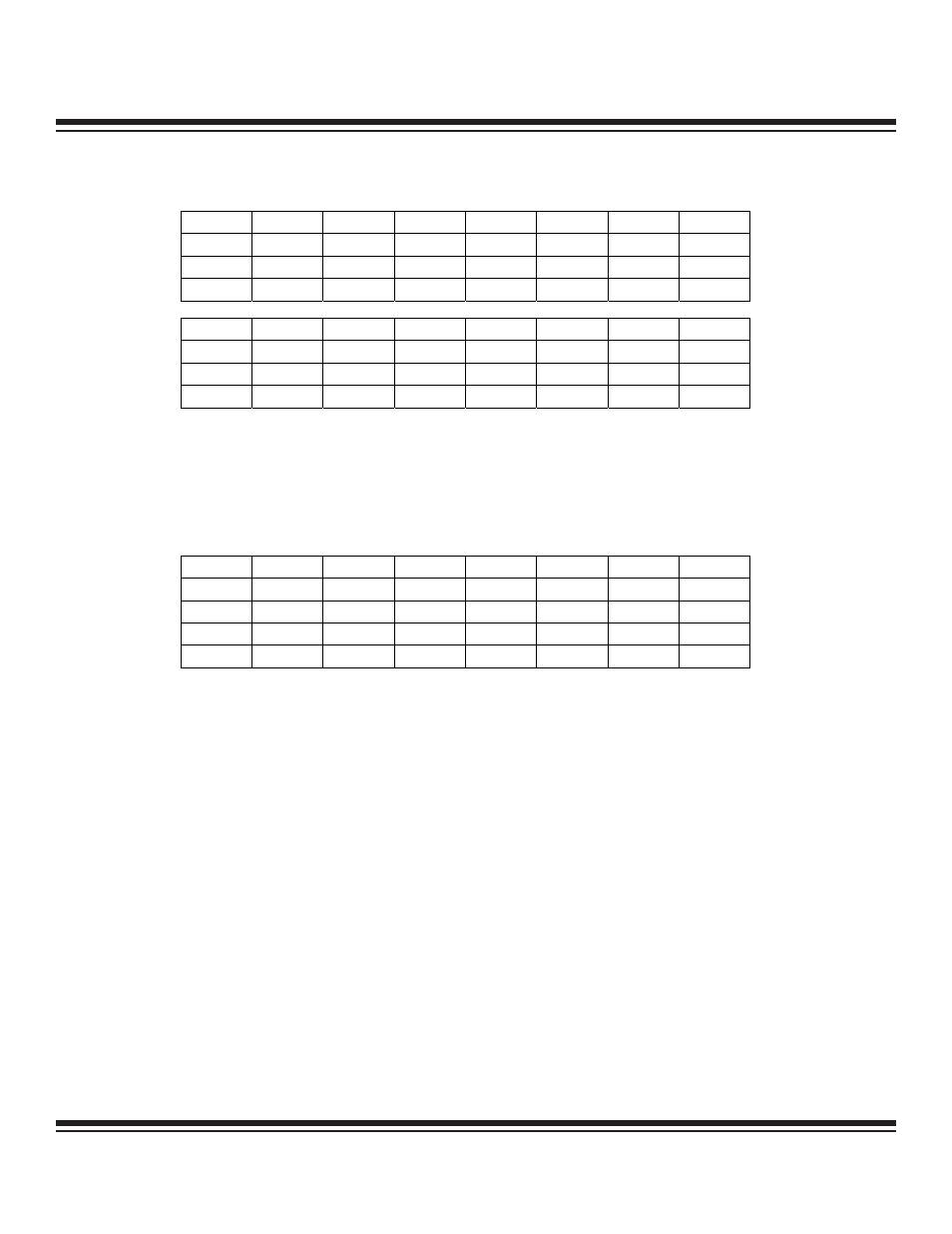
14.4.7 RTC Sub-Second Alarm Register (RSSA)
Bits 15 to 0: RTC Sub-Second Alarm (RSSA.[15:0]). This register contains the reload value for the sub-second alarm. The ALSF bit
is set when an auto-reload occurs. The width of the RSSA register for any given MAXQ microcontroller and hence, the longest pro-
grammable interval, is device dependent. This register is write-accessible only when ASE = 0 and BUSY = 0.
14.4.8 RTC Trim Register (RTRM)
Bits 7 and 6: Reserved
Bit 5: Trim Sign Bit (TSGN). This register bit selects whether the trim calibration for the RTC is positive (TSGN = 0) or negative
(TSGN = 1). The trim bits are always readable, but are write-accessible only when WE = 1.
Bits 4 to 0: Trim Calibration Bits (TRM[4:0]). These register bits provide a binary value between 0b–31b, which is used for accu-
mulation every 16 seconds. The carry-out of the accumulation determines when an additional 128 32kHz-input clock cycles are
added/subtracted to the RTC counter chain. The trim bits are always readable, but are write-accessible only when WE = 1.
14-10
MAXQ Family User’s Guide
Bit #
15
14
13
12
11
10
9
8
Name
RSSA.15
RSSA.14
RSSA.13
RSSA.12
RSSA.11
RSSA.10
RSSA.9
RSSA.8
Reset
0
0
0
0
0
0
0
0
Access
rs
rs
rs
rs
rs
rs
rs
rs
Bit #
7
6
5
4
3
2
1
0
Name
RSSA.7
RSSA.6
RSSA.5
RSSA.4
RSSA.3
RSSA.2
RSSA.1
RSSA.0
Reset
0
0
0
0
0
0
0
0
Access
rs
rs
rs
rs
rs
rs
rs
rs
r = read, s = special
Bit #
7
6
5
4
3
2
1
0
Name
—
—
TSGN
TRM4
TRM3
TRM2
TRM1
TRM0
Power-On Reset
0
0
0
0
0
0
0
0
Reset
0
0
u
u
u
u
u
u
Access
r
r
rs
rs
rs
rs
rs
rs
r = read, s = special, u = unaffected
Maxim Integrated