3 processor status flags r, 4 interrupt and control re, 5 interrupt mask register – Maxim Integrated MAXQ Family User Manual
Page 49: 3 processor status flags register (psf, 8h[4h]) -3, 4 interrupt and control register (ic, 8h[5h]) -3, 5 interrupt mask register (imr, 8h[6h]) -3, Maxq family user’s guide, 3 processor status flags register (psf, 8h[4h]), 4 interrupt and control register (ic, 8h[5h]), 5 interrupt mask register (imr, 8h[6h])
4-3
MAXQ Family User’s Guide
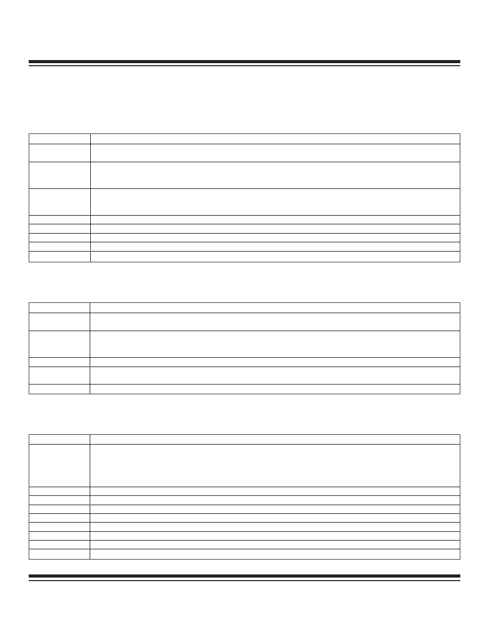
4.3 Processor Status Flags Register (PSF, 8h[4h])
The OV and S bit definitions are given for the MAXQ20 (16-bit accumulators and ALU).
Initialization: This register is cleared to 80h on all forms of reset.
Access: Bit 7 (Z), bit 6 (S), and bit 2 (OV) are read only. Bits 4 and 3 (GPF1,GPF0), bit 1 (C), and bit 0 (E) are unrestricted read/write.
4.4 Interrupt and Control Register (IC, 8h[5h])
Initialization: This register is cleared to 00h on all forms of reset.
Access: Unrestricted direct read/write access.
4.5 Interrupt Mask Register (IMR, 8h[6h])
Initialization: This register is cleared to 00h on all forms of reset.
Access: Unrestricted read/write access.
BIT
FUNCTION
IC.0 (IGE)
Interrupt Global Enable. If this bit is set to 1, interrupts are globally enabled, but still must be locally enabled to occur. If this bit is
set to 0, all interrupts are disabled.
IC.1 (INS)
Interrupt In Service. The INS is set by hardware automatically when an interrupt is acknowledged. No further interrupts occur as
long as the INS remains set. The interrupt service routine can clear the INS bit to allow interrupt nesting. Otherwise, the INS bit is
cleared by hardware upon execution of an RETI or POPI instruction.
IC.4 to IC.2
Reserved. All reads return 0.
IC.5 (CGDS)
System Clock Gating Disable. If this bit is set to 0 (default mode), system clock gating circuitry is active. If this bit is set to 1, the
clock gating circuitry is disabled.
IC.7, IC.6
Reserved. All reads return 0.
BIT
FUNCTION
The first six bits in this register are interrupt mask bits for modules 0 to 5, one bit per module. The eighth bit, IMS, serves as a
mask for any system module interrupt sources. Setting a mask bit allows the enabled interrupt sources for the associated module
or system (for the case of IMS) to generate interrupt requests. Clearing the mask bit effectively disables all interrupt sources
associated with that specific module or all system interrupt sources (for the case of IMS). The interrupt mask register is intended
to facilitate user-definable interrupt prioritization.
IMR.0 (IM0)
Interrupt Mask for Register Module 0
IMR.1 (IM1)
Interrupt Mask for Register Module 1
IMR.2 (IM2)
Interrupt Mask for Register Module 2
IMR.3 (IM3)
Interrupt Mask for Register Module 3
IMR.4 (IM4)
Interrupt Mask for Register Module 4
IMR.5 (IM5)
Interrupt Mask for Register Module 5
IMR.6
Reserved. Reads return 0.
IMR.7 (IMS)
Interrupt Mask for System Modules
BIT
FUNCTION
PSF.0 (E)
Equals Flag. This bit flag is set to 1 whenever a compare operation (CMP) returns an equal result. If a CMP operation returns not
equal, this bit is cleared.
PSF.1 (C)
Carry Flag. This bit flag is set to 1 whenever an add or subtract operation (ADD, ADDC, SUB, SUBB) returns a carry or borrow.
This bit flag is cleared to 0 whenever an add or subtract operation does not return a carry or borrow. Many other instructions
potentially affect the carry bit. Reference the instruction set documentation for details.
PSF.2 (OV)
Overflow Flag. This flag is set to 1 if there is a carry out of bit 14 but not out of bit 15, or a carry out of bit 15 but not out of bit 14
from the last arithmetic operation, otherwise, the OV flag remains as 0. OV indicates a negative number resulted as the sum of
two positive operands, or a positive sum resulted from two negative operands.
PSF.3 (GPF0)
General Purpose Flag 0
PSF.4 (GPF1)
General Purpose Flag 1. These general-purpose flag bits are provided for user software control.
PSF.5
Reserved. All reads return 0.
PSF.6 (S)
Sign Flag. This bit flag mirrors the current value of the high bit of the active accumulator (Acc.15).
PSF.7 (Z)
Zero Flag. The value of this bit flag equals 1 whenever the active accumulator is equal to zero, and it equals 0 otherwise.
Maxim Integrated