Figure 14-1. rtc functional block diagram -2, Maxq family user’s guide – Maxim Integrated MAXQ Family User Manual
Page 143
14-2
MAXQ Family User’s Guide
SECTION 14: REAL-TIME CLOCK MODULE
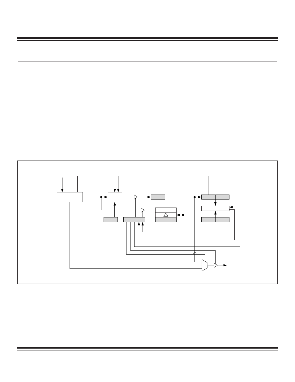
The real-time clock (RTC) is a binary timer that keeps the time of day and provides time-of-day and sub-second alarm functionality in
the form of system interrupts. The RTC consists of cascaded 32-bit and 8-bit ripple counters that respectively represent absolute sec-
onds (~136 years) and sub-seconds (in 1/256 second resolution). The 8-bit sub-second counter increments with each 256Hz clock tick
derived from the 32.768kHz oscillator. A separate auto-reload sub-second alarm counter can be used to generate interval alarms with
granularity of 1/256 seconds. The 32-bit seconds counter increments with each rollover of the 8-bit sub-second counter. The 32-bit
counter can be used with the programmable time-of-day comparison alarm to provide a single event timer. The RTC must be stopped
for the counter registers to initially be written, but once enabled, the RTC counts continuously as long as it is enabled and does not stop
for reads of the counter registers. The RTC also supports a digital trim facility for those applications requiring high accuracy.
User-application code accesses the RTC via eight peripheral registers. The 16-bit RTC Control register (RCNT) provides the control
and status for RTC functions, including RTC read/write access controls, clock selection/control, RTC enable, square-wave output
enable, alarm enables, and their interrupt flags. The seconds count information is set or initialized only by writing to the 16-bit RTC
Second High and the 16-bit RTC Second Low register (RTSH and RTSL registers). Similarly, the 8-bit RTC Sub-Second register (RTSS)
can be used to establish and access the sub-second counter. The Time-of-Day alarm is composed of the RASH:RASL register pair
and the interval alarm is programmable via the RSSA register. The digital trim value is held in the RTRM register.
Figure 14-1 shows a functional diagram of a full-featured RTC. Certain MAXQ microcontroller devices may be equipped with a subset
of the RTC functionality described. Refer to the individual device data sheet or supplemental user guide for more information.
DIGITAL
TRIM
DIVIDE BY 128(2
7
)
1/256Hz
32kHz CLK
1/512Hz
1Hz
1/512Hz
RTRM
RTSS
RSSA
RTSL
RTSH
RASL
RASH
COMPARE
RCNT
ADE
ALDF
ALSF
RTCE
ASE
TSGN, TRM4: 0
SQE
FT
SQUARE-
WAVE OUT
Figure 14-1. RTC Functional Block Diagram
Maxim Integrated