2 rtc seconds high regi, 2 rtc seconds high register (rtsh) -7, Maxq family user’s guide – Maxim Integrated MAXQ Family User Manual
Page 148: 2 rtc seconds high register (rtsh)
14-7
MAXQ Family User’s Guide
Bit 3: RTC Busy (BUSY). This bit is set to 1 by hardware when any of the following conditions occur: 1) system reset, 2) software writes
to RTC count registers, or 3) software changes RTCE, ASE, or ADE. For conditions 2 and 3, the write or change should not be con-
sidered complete until hardware clears the BUSY bit. This is an indication that 32kHz synchronized version of the register bit(s) is in
place.
Bit 2: Alarm Sub-Second Enable (ASE). The ASE bit is the RTC’s subsecond timer enable and must be set to logic 1 for the sub-sec-
ond alarm to generate a system interrupt request. When the ASE is cleared to logic 0, the sub-second alarm is disabled, and no inter-
rupt is generated even if the alarm is set.
Bit 1: Alarm Time-of-Day Enable (ADE). The ADE bit is the RTC’s time-of-day alarm enable and must be set to logic 1 for the alarm
to generate a system interrupt request. When the ADE is cleared to logic 0, the time-of-day alarm is disabled and no interrupt is gen-
erated on a time-of-day alarm (RASH:RASL) match.
Bit 0: Real-Time Clock Enable (RTCE). Setting this bit to logic 1 activates the RTC by allowing the 256Hz clock to the ripple coun-
ters. Clearing this bit to logic 0 disables the clock. This bit is writable only when WE (RCNT.15) = 1.
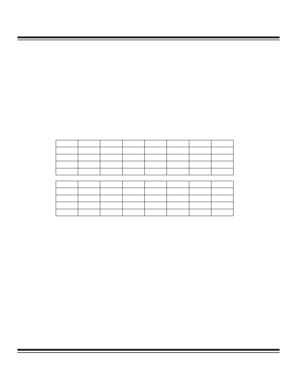
14.4.2 RTC Seconds High Register (RTSH)
Bits 15 to 0: RTC Seconds High (RTSH.[15:0]). This register contains the most significant bits for the 32-bit second counter. The RTC
is a ripple counter that consists of a cascaded 32-bit second counter (RTSH, RTSL) and an 8-bit sub-second counter (RTSS). This reg-
ister is write-accessible when RTCE = 0 and BUSY = 0, and should be read-only when RDY = 1.
Bit #
15
14
13
12
11
10
9
8
Name
RTSH.15
RTSH.14
RTSH.13
RTSH.12
RTSH.11
RTSH.10
RTSH.9
RTSH.8
Power-On Reset
0
0
0
0
0
0
0
0
System Reset
u
u
u
u
u
u
u
u
Access
s
s
s
s
s
s
s
s
Bit #
7
6
5
4
3
2
1
0
Name
RTSH.7
RTSH.6
RTSH.5
RTSH.4
RTSH.3
RTSH.2
RTSH.1
RTSH.0
Power-On Reset
0
0
0
0
0
0
0
0
System Reset
u
u
u
u
u
u
u
u
Access
s
s
s
s
s
s
s
s
s = special, u = unaffected
Maxim Integrated