4 external rc, 5 internal system clock, 4 external rc -15 – Maxim Integrated MAXQ Family User Manual
Page 20: 5 internal system clock generation -15, Figure 2-8. on-chip crystal oscillator -15, Figure 2-9. rc relaxation oscillator -15, Table 2-2. system clock rate control settings -15, Maxq family user’s guide, Table 2-2. system clock rate control settings, 5 internal system clock generation
2-15
resistor to ensure a satisfactory logic level for active clock pulses. To minimize system noise on the clock circuitry, the external clock
source must meet the maximum rise and fall times and the minimum high and low times specified for the clock source. The external
noise can affect clock generation circuit if these parameters do not meet the specification.
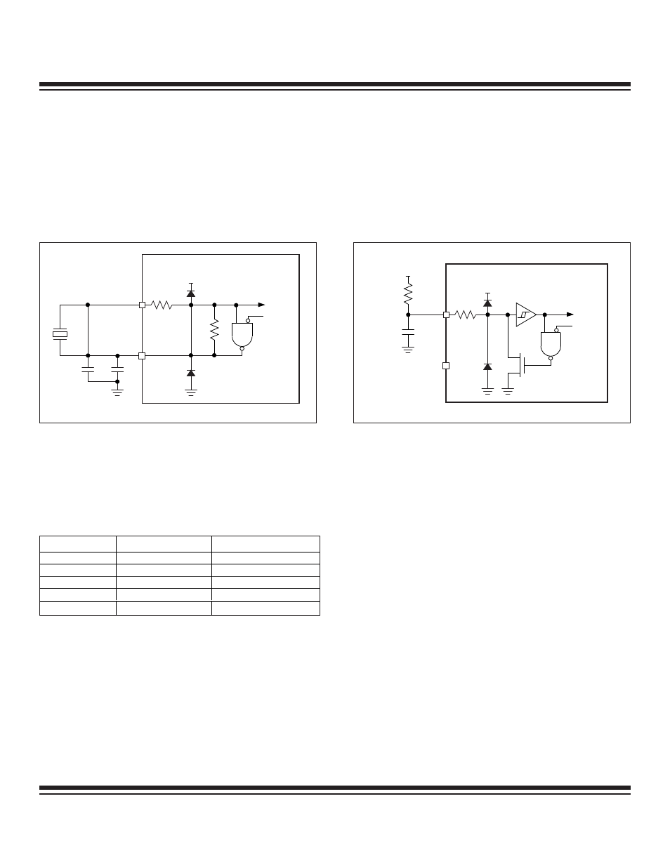
2.7.4 External RC
For timing-insensitive applications, the external RC option offers additional cost savings. The RC oscillator frequency is a function of
the supply voltage, external resistor (Rext) and capacitor (Cext) values and tolerances, and the operating temperature. In addition to
this, the oscillator frequency varies from unit to unit due to normal process parameter variation. Figure 2-9 shows how the external RC
combination is connected to the MAXQ microcontroller.
2.7.5 Internal System Clock Generation
The internal system clock is derived from the currently selected oscillator input.
By default, one system clock cycle is generated per oscillator cycle, but the number of oscillator cycles per system clock can also be
increased by setting the Power Management Mode Enable (PMME) bit and the Clock Divide Control (CD[1:0]) register bits per Table 2-2.
Table 2-2. System Clock Rate Control Settings
PMME
CD[1:0]
CYCLES PER CLOCK
0
00
1 (default)
0
01
2
0
10
4
0
11
8
1
xx
256
Figure 2-9. RC Relaxation Oscillator
MAXQ
CLOCK
CIRCUITRY
STOP OR
RGSL
V
CC
V
CC
XTAL1
XTAL2
INTERNAL CIRCUIT
R
EXT
C
EXT
MAXQ Family User’s Guide
Figure 2-8. On-Chip Crystal Oscillator
MAXQ
CLOCK
CIRCUITRY
STOP OR
RGSL
V
CC
XTAL1
XTAL2
C1
C2
INTERNAL CIRCUIT
R
F
Maxim Integrated