4 timer 0 mode: two 8-bi, 4 timer 0 mode: two 8-bit timer/counters -4, Figure 7-3. timer/counter 0 dual 8-bit mode -4 – Maxim Integrated MAXQ Family User Manual
Page 69: Maxq family user’s guide, 4 timer 0 mode: two 8-bit timer/counters
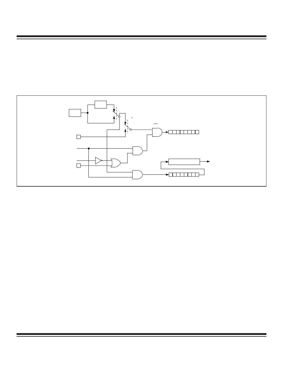
7.1.4 Timer 0 Mode: Two 8-Bit Timer/Counters
When T0CN register bits M1:M0 = 11b, Timer 0 provides two 8-bit timer/counters as shown in Figure 7-3. In this mode, T0L is an 8-bit
timer/counter that can be used to count clock cycles or 1-to-0 transitions on pin T0 as determined by C/T. (T0CN.2). As in the other
modes, the GATE function can use T0G to give external run control of the timer to an outside signal.
T0H becomes an independent 8-bit timer that can only count clock cycles as shown in Figure 7-3. The clock-input enable for both
timer/counters (T0L and T0H) is controlled by the Timer 0 Run (TR0) bit, while the Timer 0 interrupt flag bit (TF0) is associated only with
rollover of the T0H register.
7-4
MAXQ Family User’s Guide
TR0 = T0CN.4
CLK
0
0
7
7
T0L
0
1
1
C/T = T0CN.2
INTERRUPT
T0M = T0CN.6
T0G PIN
T0 PIN
GATE = T0CN.3
DIVIDE
BY 12
SYSTEM
CLOCK
TF0 = T0CN.5
0
T0H
Figure 7-3. Timer/Counter 0 Dual 8-Bit Mode
Maxim Integrated