2 timer/counter 0 peripher, 1 timer/counter 0 contro, 2 timer/counter 0 peripheral registers -5 – Maxim Integrated MAXQ Family User Manual
Page 70: 1 timer/counter 0 control register (t0cn) -5, Maxq family user’s guide, 2 timer/counter 0 peripheral registers, 1 timer/counter 0 control register (t0cn)
7.2 Timer/Counter 0 Peripheral Registers
7.2.1 Timer/Counter 0 Control Register (T0CN)
Bit 7: Enable Timer 0 Interrupt (ET0). Setting this bit to 1 enables interrupts from the Timer 0 TF0 flag. Clearing this bit to 0 disables
the Timer 0 interrupt.
Bit 6: Timer 0 Clock Select (T0M). The T0M bit selects the clock frequency for Timer 0:
0 = Uses a divide by 12 of the system clock frequency as Timer 0 base clock.
1 = Uses a divide by 1 of the system clock frequency as Timer 0 base clock.
Bit 5: Timer 0 Overflow Flag (TF0). This bit is set to 1 when Timer 0 overflows its maximum count as defined by the current mode. It
is cleared either by software or a reset. When this bit is 0, no Timer 0 overflow has been detected.
Bit 4: Timer 0 Run Control (TR0). Setting this bit enables Timer/Counter 0. Clearing this bit halts the Timer/Counter 0.
Bit 3: Timer 0 Gate Control (GATE)
0 = Timer 0 will clock when TR0 is 1, regardless of the logic state of the external T0G gating control pin
1 = Timer 0 will clock only when TR0 and the logic state of the external T0G gating control pin are 1
Bit 2: Counter/Timer 0 Select (C/
T)
0 = Selects timer function with internal clock when TR0 is 1
1 = Selects counter function with external T0 input when TR0 is 1
Bits 1 and 0: (M[1:0]). These mode select bits define the Timer/Counter mode of operation:
7-5
MAXQ Family User’s Guide
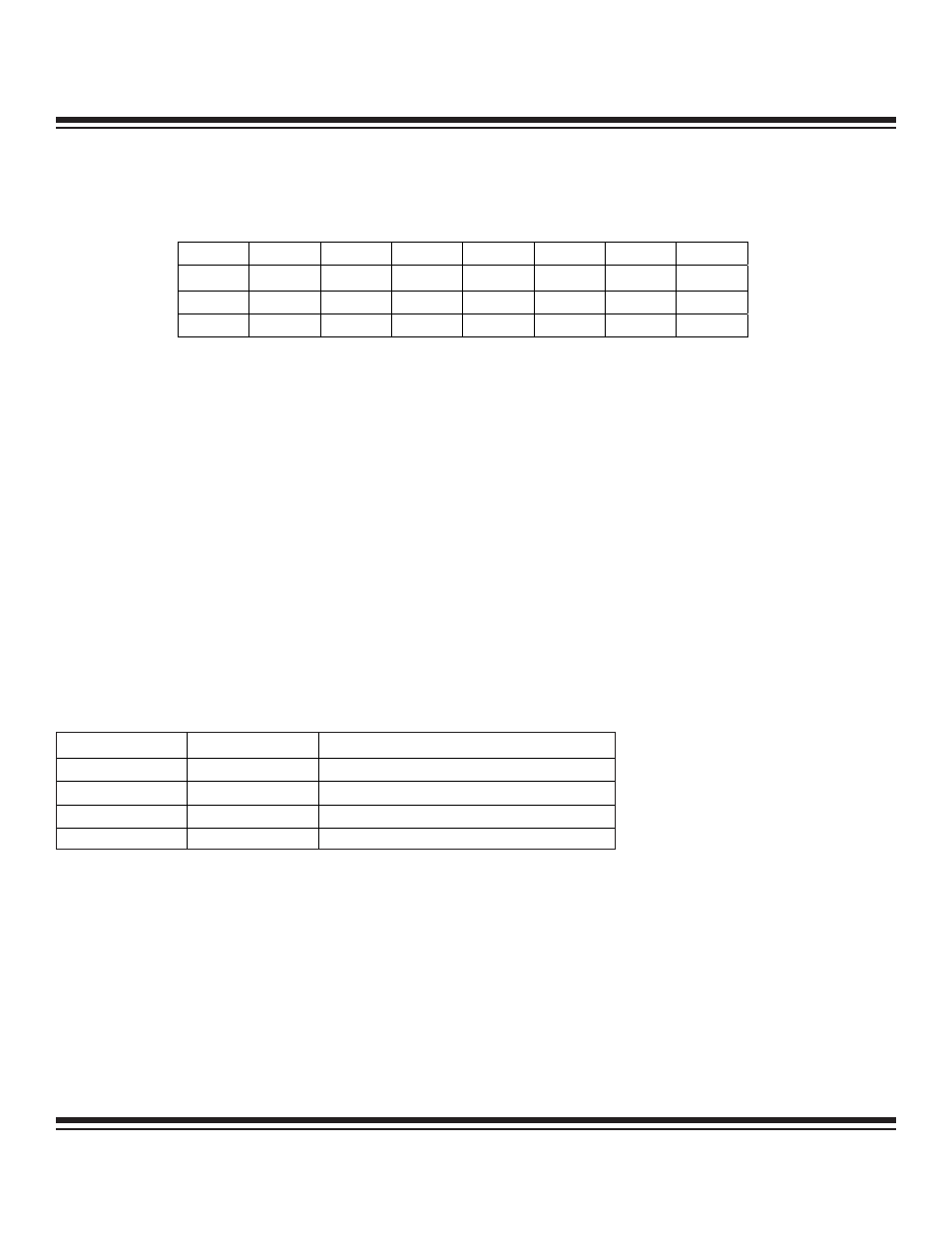
Bit #
7
6
5
4
3
2
1
0
Name
ET0
T0M
TF0
TR0
GATE
C/T
M1
M0
Reset
0
0
0
0
0
0
0
0
Access
rw
rw
rw
rw
rw
rw
rw
rw
r = read, w = write
M1
M0
FUNCTION
0
0
Mode 0: 8-Bit with 5-Bit Prescale
0
1
Mode 1: 16-Bit with No Prescale
1
0
Mode 2: 8-Bit with Auto-Reload
1
1
Mode 3: Two 8-Bit Timers
Maxim Integrated