6 timer/counter 1 mode r, 3 time-base selection for, 6 timer/counter 1 mode register (t1md) -7 – Maxim Integrated MAXQ Family User Manual
Page 78: 3 time-base selection for timers 0 and 1 -7, Maxq family user’s guide, 3 time-base selection for timers 0 and 1, 6 timer/counter 1 mode register (t1md)
8.2.6 Timer/Counter 1 Mode Register (T1MD)
Bits 7 to 2: Reserved
Bit 1: Enable Timer 1 Interrupt (ET1). Setting this bit to 1 enables interrupts from the Timer 1 TF1 and EXF1 flags in T1CN. The EXF1
flag does not cause interrupts in the up/down count mode.
Bit 0: Timer 1 Clock Select (T1M). The T0M bit selects the clock frequency for Timer 1:
0 = Uses a divide by 12 of the system clock frequency as Timer 1 base clock
1 = Uses a divide by 1 of the system clock frequency as Timer 1 base clock
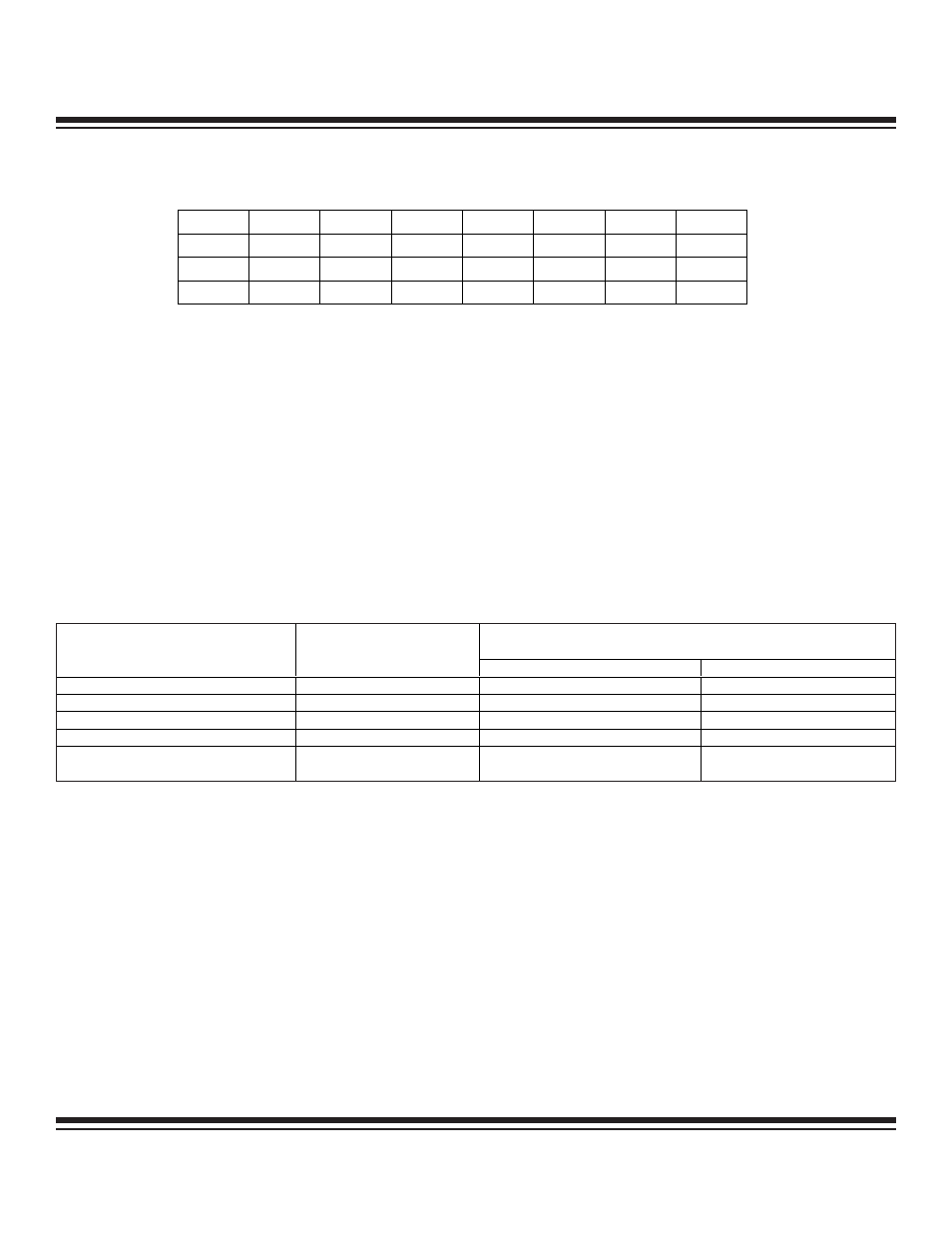
8.3 Time-Base Selection for Timers 0 and 1
The MAXQ allows selection of the time base for each timer independently. The input clock for each timer defaults to 12 system clocks
per timer tick. The timer-input clock frequency can be increased by setting the respective TxM bit for the timer (T0M for Timer 0; T1M
for Timer 1). Setting the TxM bit allows the system clock input to be used for the timer-input clock. Table 8-2 shows the resulting timer
input clock for the various system clock modes according to timer control bit TxM setting.
Table 8-2. Input Clock Frequency Selection for Timer 0 and Timer 1
8-7
MAXQ Family User’s Guide
TIMER 0, 1
INPUT CLOCK FREQUENCY
SYSTEM CLOCK MODE
SYSTEM CLOCK SELECT
BITS PMME, CD1, CD0
TxM = 0
TxM = 1
Divide by 1
000
CLK / 12
CLK / 1
Divide by 2
001
CLK / 24
CLK / 2
Divide by 4
010
CLK / 48
CLK / 4
Divide by 8
011
CLK / 96
CLK / 8
Power Management Mode
(Divide by 256)
1xx
CLK / 3072
CLK / 256
Bit #
7
6
5
4
3
2
1
0
Name
—
—
—
—
—
—
ET1
T1M
Reset
0
0
0
0
0
0
0
0
Access
r
r
r
r
r
r
rw
rw
r = read, w = write
Maxim Integrated