1 hardware multiplier org, 1 hardware multiplier organization -2, Figure 12-1. multiplier organization -2 – Maxim Integrated MAXQ Family User Manual
Page 122: Maxq family user’s guide, 1 hardware multiplier organization
12-2
MAXQ Family User’s Guide
SECTION 12: HARDWARE MULTIPLIER MODULE
The hardware multiplier module can be used by the MAXQ microcontroller to support high-speed multiplications. The hardware multi-
plier module is equipped with two 16-bit operand registers, a 32-bit read-only result register, and an accumulator of width between 32
bits and 48 bits, depending on the specific MAXQ device. The multiplier can complete a 16-bit x 16-bit multiply-and-accumulate/sub-
tract operation in a single cycle. The hardware multiplier module supports the following operations without interfering with the normal
core functions:
• Signed or unsigned Multiply (16 bit x 16 bit)
• Signed or unsigned Multiply-Accumulate (16 bit x 16 bit)
• Signed or unsigned Multiply-Subtract (16 bit x 16 bit)
• Signed Multiply and Negate (16 bit x 16 bit)
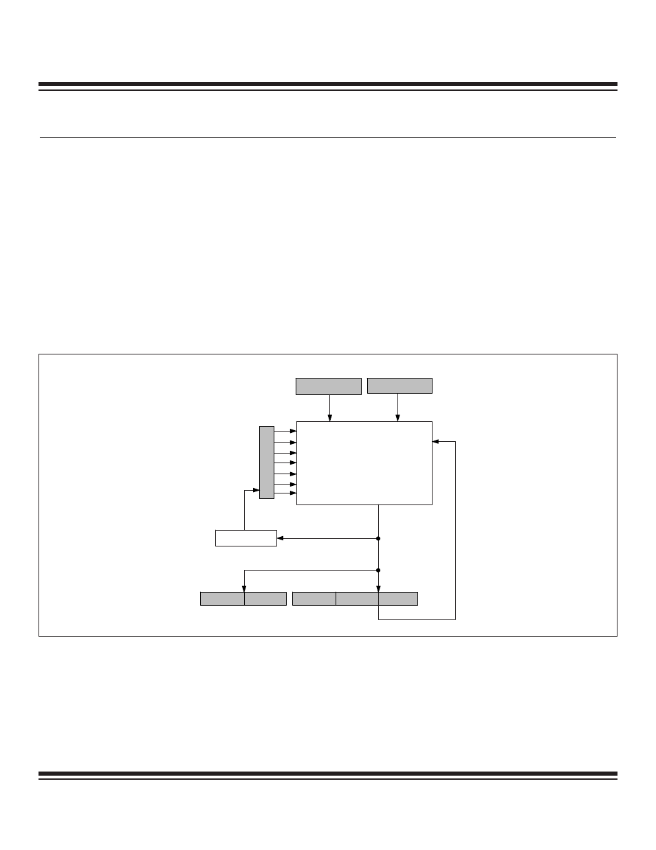
12.1 Hardware Multiplier Organization
The hardware multiplier consists of two 16-bit, parallel-load operand registers (MA, MB); a read-only result register formed by two paral-
lel 16-bit registers (MC1R and MC0R); an accumulator, which is formed by up to three 16-bit parallel registers (MC2, MC1, and MC0); and
a status/control register (MCNT). Note that the width and/or presence of the MC2 register depend on the specified accumulator size for
the given MAXQ device. Figure 12-1 shows a block diagram of the hardware multiplier.
MB
MA
MC0
MC1
MC2
MULTIPLIER
0
0
15
15
0
15
0
15
OVERFLOW
SUS
MMAC
MSUB
OPCS
SQU
CLD
MCW
15
0
15
15
0
0
MC1R
MC0R
MCNT
Figure 12-1. Multiplier Organization
Maxim Integrated