Table 13-2. rom id read time slot possibilities -7, Maxq family user’s guide, Table 13-2. rom id read time slot possibilities – Maxim Integrated MAXQ Family User Manual
Page 136
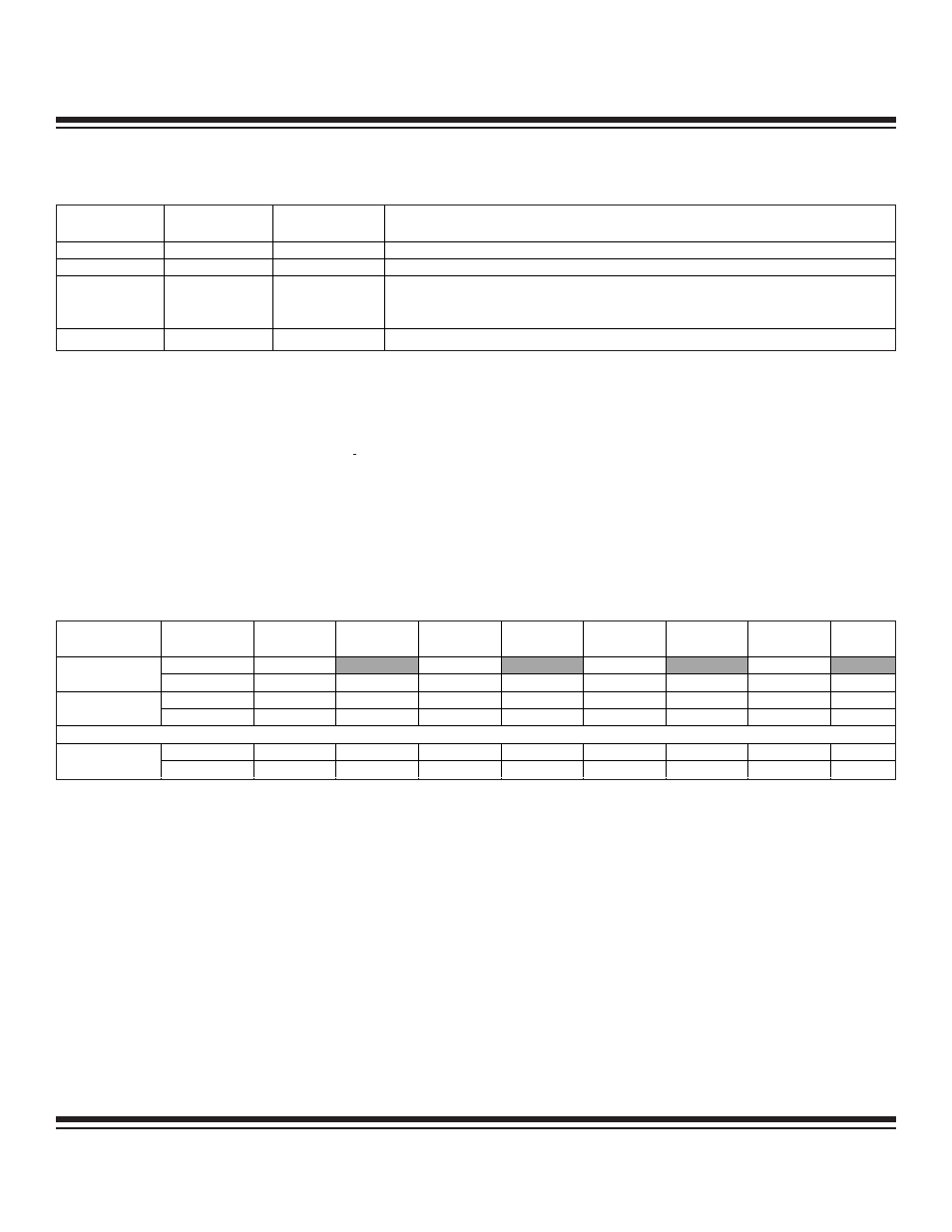
Table 13-2. ROM ID Read Time Slot Possibilities
The general principle of this search process is to deselect slave devices at every conflicting bit position. At the end of each ROM
Search process, the master has learned another ROM ID. A pass of search process takes 64 reading/selection cycles for the master
to learn one device's ROM ID. Each reading/selection cycle, as noted above, consists of two Read time slots and a Write time slot.
Subsequent search passes are performed identically to the last up until the point of the last decision. For details of Search ROM algo-
rithm in the 1-Wire system, refer to the Book of iButton Standards.
To speed up this ROM ID Search process, the 1-Wire Bus Master incorporates a Search ROM Accelerator. To enable the Search ROM
accelerator, the SRA bit in the Command Register must be set immediately following the Reset sequence and issuance of the Search ROM
command. Note that the receive buffer must empty before invoking SRA mode. After the bus master is placed in Search ROM Accelerator
mode, each byte loaded into the transmit buffer contains one nibble (4 bits) worth of discrepancy decision data. The two slave read time
slots are automatically generated by the bus master as a part of the transmit sequence. After four reading/selection cycles, the receive
buffer data will reflect four newly acquired bits of the ROM ID and four corresponding bits flagging whether a discrepancy existed in a
given bit position. Table 13-3 details the format for the transmit and receive data (when in Search ROM Accelerator mode).
Table 13-3. Search ROM Accelerator Transmit/Receive Byte Sequence
The CPU must send and receive 16 bytes of data to complete a single Search ROM pass on the 1-Wire bus. To perform a Search ROM
sequence one starts with all decision discrepancy bits (r
n
) being 0. In case of bus error, all subsequent response bits IDn are 1s until
the Search Accelerator is deactivated by clearing the SRA bit in the Command Register. Thus if ID
63
and d
63
are both 1, an error has
occurred during the search process and the last sequence has to be repeated. Otherwise, ID
63:0
is the ROM code of the device that
has been found and addressed. For the next Search ROM sequence one reuses the previous set r
n
(for n = 0:63), changing to 1 only
that bit position where the highest discrepancy was detected (d
n
flags). This process is repeated until the highest discrepancy occurs
in the same bit position for two passes, then the next lower discrepancy flag is used for next search. When the Search ROM process
is completed, the SRA bit should be cleared in order to release the 1-Wire Master from Search ROM Accelerator mode.
13-7
MAXQ Family User’s Guide
READ TIME
SLOT 1 (SLAVE
)
READ TIME
SLOT 2 (SLAVE)
WRITE TIME
SLOT (MASTER)
DESCRIPTION
0
1
0
All slave devices remaining in the selection process have a 0 in this ROM ID bit position.
1
0
1
All slave devices remaining in the selection process have a 1 in this ROM ID bit position.
0
0
0 or 1
ID Discrepancy—Slave devices remaining in the selection process have both 0 and
1 in this ROM ID bit position. The Bus Master write time slot dictates which devices
remain in the selection process.
1
1
1
Error—No slave devices responded during the read time slots.
BYTE
SEQUENCE
BUFFER
BIT 7
BIT 6
BIT 5
BIT 4
BIT 3
BIT 2
BIT 1
BIT 0
Transmit
r
3
x
r
2
x
r
1
x
r
0
x
Byte 1
Receive
ID
3
d
3
ID
2
d
2
ID
1
d
1
ID
0
d
0
Transmit
r
7
x
r
6
x
r
5
x
r
4
x
Byte 2
Receive
ID
7
d
7
ID
6
d
6
ID
5
d
5
ID
4
d
4
• • •
Transmit
r
63
x
r
62
x
r
61
x
r
60
x
Byte 16
Receive
ID
63
d
63
ID
62
d
62
ID
61
d
61
ID
60
d
60
r
n
= decision discrepancy data (write time slot selection data if ID discrepancy)
ID
n
= selected ROM ID bit (r
n
if discrepancy occurred, otherwise read time slot 1)
d
n
= discrepancy detected flag (ID discrepancy or no response)
x = don't care data
Maxim Integrated