1 timer 2, 1 timer 2 -4, Maxq family user’s guide – Maxim Integrated MAXQ Family User Manual
Page 82: Table 9-1. timer/counter 2 functions and control
9-4
MAXQ Family User’s Guide
SECTION 9: TIMER/COUNTER 2 MODULE
The Timer/Counter 2 Module provides a 16-bit programmable timer/counter with pulse-width modulation capability. Whether and how
many Timer 2 Modules are implemented in a given MAXQ-based microcontroller is product dependent.
Timer 2 is an auto-reload, 16-bit timer/counter offering the following functions:
• 8-bit/16-bit timer/counter
•
capture
• up/down auto-reload
•
compare
• counter function of external pulse
•
input/output enhancements
9.1 Timer 2
The 16-bit Timer 2 value is contained in the T2V register. The upper byte is always accessible through the T2H 8-bit register. When Timer 2
is operated in the dual 8-bit mode of operation, the high byte of T2V always reads x00h and is not write accessible. The low byte of the T2V
will often be referenced as T2L. Similar registers and nomenclature are used for the Timer 2 auto-reload value resides in the T2R register. A
separate 8-bit T2RH register allows read/write access to the high byte and the low byte of T2R is often referred to as T2RL. The
Capture/Compare functionality is supported by Timer 2 through the 16-bit T2C capture register and the 8-bit T2CH high-byte access regis-
ter. Timer 2 normally requires two pins to support the enhanced input/output functionality. Throughout this section the primary input/output
pin will be referred to as T2P and the secondary pin, which may or may not be present for a given device, will be referred to as T2PB.
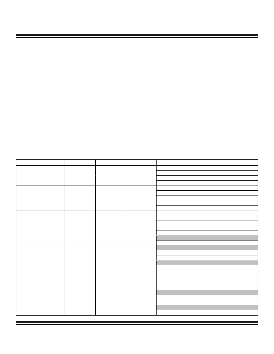
Decision whether and/or where to implement the T2PB pin functionality is product and application dependent. Table 9-1 summarizes the
modes supported by Timer 2 and the peripheral register bits associated with those modes.
Table 9-1. Timer/Counter 2 Functions and Control
MODE
T2MD
C/T2
CCF[1:0]
CONTROL BITS
T2OE[1:0]—output enables (PWM out)
T2POL[1:0]—input/output polarity select
SS2—single-shot pulse control
16-Bit Auto-
Reload/Compare Timer
0
0
00
G2EN—gated PWM output
T2OE[0] = 0
T2POL[0]—gate level/reload edge select
SS2—single-shot capture
G2EN—gate timer clock (or gate reload)
16-Bit Capture (CCF[1:0]
bits define capture edge)
0
0
01, 10, or 11
CPRL2—reload enable
T2OE[0] = 0
T2OE[1]—pulse counter output
16-Bit Counter (CCF[1:0]
bits define count edge)
0
1
01, 10, or 11
T2POL[1]—output polarity select
T2OE[1:0]—output enables (PWM out)
T2POL[1:0]—output polarity select
T2H Only:
Dual 8-Bit Auto-Reload
Timers
1
0
00
SS2—single-shot pulse control
T2L Only:
T2OE[1]—output enable
T2POL[1]—output polarity select
T2H Only:
T2OE[0] = 0
T2POL[0]—gate level/reload edge select
SS2—single-shot capture
G2EN—gate timer (or gate reload)
8-Bit Capture and 8-Bit
Timer/PWM
1
0
01, 10, or 11
CPRL2—reload enable
T2L Only:
T2OE[1]—output enable
T2POL[1]—output polarity select
T2H Only:
8-Bit Counter and 8-Bit
Timer/PWM
1
1
01, 10, or 11
T2OE[0] = 0
Maxim Integrated