Maxq family user’s guide – Maxim Integrated MAXQ Family User Manual
Page 131
13-2
MAXQ Family User’s Guide
SECTION 13: 1-Wire BUS MASTER
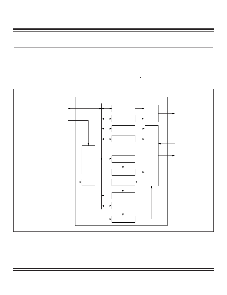
The 1-Wire Bus Master can be used by the MAXQ microcontroller to support 1-Wire communication to external 1-Wire devices without
tying up valuable CPU resources. The Bus Master provides complete control of the 1-Wire bus, and transmit and receive activities. All tim-
ing and control sequences of the 1-Wire bus are generated within the Bus Master. Communication between the CPU and the Bus Master
is through read/write access of 1-Wire Master Address (OWA) and 1-Wire Master Data (OWD) peripheral registers. When bus activity has
generated a condition that requires CPU service, the Bus Master sets a status bit, allowing an interrupt to be generated if enabled. The
1-Wire Bus Master is operable for any system clock frequency between 4MHz and 25MHz, and supports the Bit Banging and Search ROM
Accelerator modes. Detailed operation of the 1-Wire bus is described in the Book of iButton Standards, available on the Maxim/Dallas
Semiconductor website at www.maxim-ic.com/iButtonbook. Figure 13-1 shows a functional block diagram of the 1-Wire Bus Master.
1-WIRE
BUS
TIMING
AND
CONTROL
INTERRUPT FLAG
INTERRUPT ENABLE
COMMAND
CONTROL
TRANSMIT BUFFER
Tx SHIFT REGISTER
Rx SHIFT REGISTER
RECEIVE BUFFER
CLOCK DIVIDER
BAUD GENERATION
INTERRUPT
CONTROL
LOGIC
CONTROL
RESET
OWD
OWA
1-WIRE MASTER
RESET
CLK
OWOUT
OWIN
MAXQ
Figure 13-1. 1-Wire Bus Master Functional Diagram
Maxim Integrated