1 accessing the multipl, 5 hardware multiplier per, 1 hardware multiplier c – Maxim Integrated MAXQ Family User Manual
Page 124: 1 accessing the multiplier -4, 5 hardware multiplier peripheral registers -4, 1 hardware multiplier control register (mcnt) -4, Table 12-1. hardware multiplier operations -4, Maxq family user’s guide, 1 accessing the multiplier, 1 hardware multiplier control register (mcnt)
12.4.1 Accessing the Multiplier
There are no restrictions on how quickly data is entered into the operand registers or the order of data entry. The only requirement to
do a calculation is to perform the loading of MA and/or MB registers having specified data type and operation in the MCNT register.
The multiplier keeps track of the writes to the MA and MB registers, and starts calculation immediately after the prescribed number of
operands is loaded. If two operands are specified for the operation, the multiplier waits for the second operand to be loaded into the
other operand register before starting the actual calculation. If for any reason software needs to reload the first operand, it should either
reload that same operand register or use the CLD bit in the MCNT register to reinitialize the multiplier; otherwise, loading data to anoth-
er operand register triggers the calculation. The CLD bit is a self-clearing bit that can be used for multiplier initialization. When it is set,
it clears all data registers and the OF bit to zero and resets the multiplier operand write counter.
The specified hardware multiplier operation begins when the final operand(s) is loaded and will complete in a single cycle. The read-
only MC1R, MC0R result registers can be accessed in the very next cycle unless accumulation/subtraction with MC2:0 is requested
(MCW = 0 and MMAC = 1), in which case, one cycle is required so that stable data can be read. When MCW = 0, the MC2:0 regis-
ters always require one wait cycle before the operation result is accessible. The single wait cycle needed for updating the MC2:0 reg-
isters with a calculated result does not prevent initiating another calculation. Back-to-back operations can be triggered (independent
of data type and operand count) without the need of wait state between loading of operands.
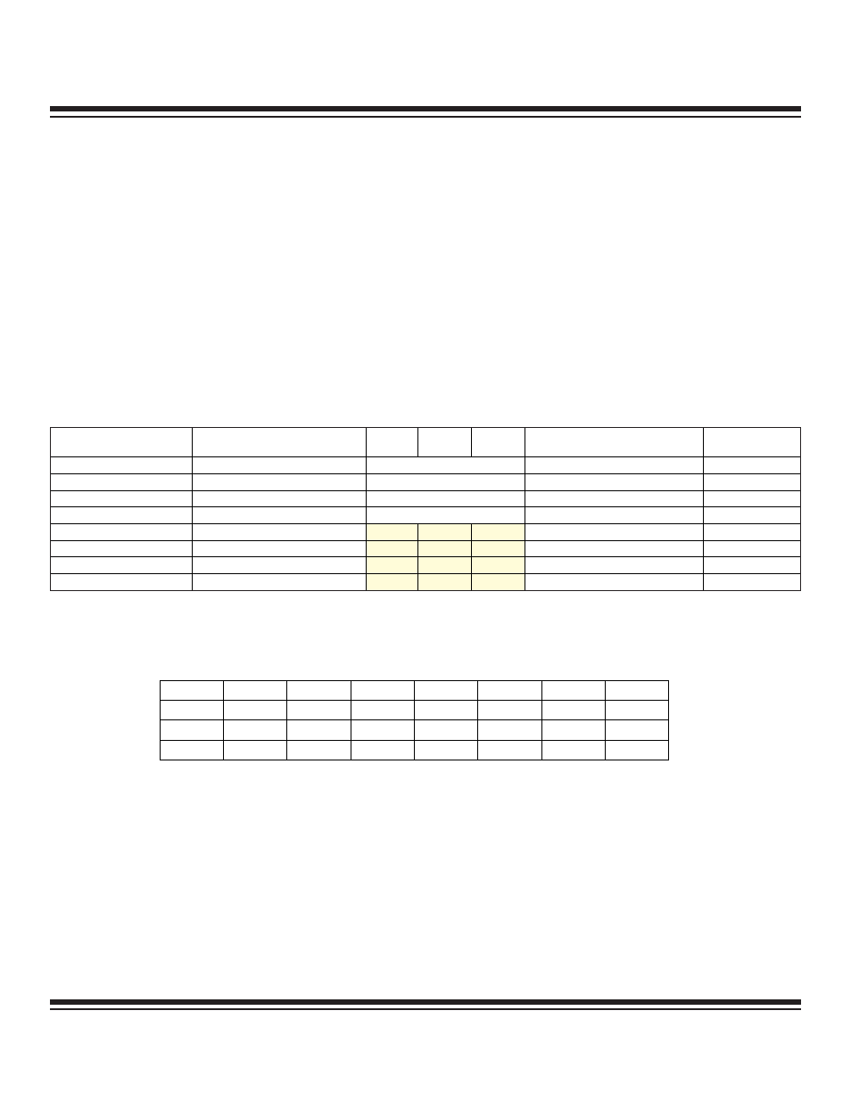
Table 12-1. Hardware Multiplier Operations
12.5 Hardware Multiplier Peripheral Registers
12.5.1 Hardware Multiplier Control Register (MCNT)
Bit 7: Overflow Flag (OF). This bit is set to logic 1 when an overflow occurred for the last operation. This bit can be set for accumu-
lation/subtraction operations or unsigned multiply-negate attempts. This bit is automatically cleared to 0 following a reset, starting a
multiplier operation, or setting of the CLD bit to 0.
Bit 6: MC Register Write Select (MCW). The state of the MCW bit determines if an operation result will be placed into the accumula-
tor registers (MC).
0 = The result will be written to the MC registers.
1 = The result is not written to the MC registers (MC register content is unchanged).
Bit 5: Clear Data Registers (CLD). This bit initializes the operand registers and the accumulator of the multiplier. When it is set to 1,
the contents of all data registers and the OF bit are cleared to 0 and the operand load counter is reset immediately. This bit is cleared
by hardware automatically. Writing a 0 to this bit has no effect.
12-4
MAXQ Family User’s Guide
MCW:MSUB:MMAC
OPERATION
MC2
MC1
MC0
MC1R:MC0R
OF
STATUS
000
Multiply
MA*MB
MA*MB
No
001
Multiply-Accumulate
MC+(MA*MB)
32lsbits of (MC+2*(MA*MB))
Yes
010
Multiply-Negate (SUS = 0 only)
-(MA*MB)
-(MA*MB)
No
011
Multiply-Subtract
MC-(MA*MB)
32lsbits of (MC-2*(MA*MB))
Yes
100
Multiply
MC2
MC1
MC0
MA*MB
No
101
Multiply-Accumulate
MC2
MC1
MC0
32lsbits of (MC+(MA*MB))
No
110
Multiply-Negate (SUS = 0 only)
MC2
MC1
MC0
-(MA*MB)
No
111
Multiply-Subtract
MC2
MC1
MC0
32lsbits of (MC-(MA*MB))
No
Bit #
7
6
5
4
3
2
1
0
Name
OF
MCW
CLD
SQU
OPCS
MSUB
MMAC
SUS
Reset
0
0
0
0
0
0
0
0
Access
r
rw
rw
rw
rw
rw
rw
rw
r = read, w = write
Maxim Integrated