3 timer 1 mode: up/down, 4 timer 1 mode: clock ou, 3 timer 1 mode: up/down count with auto-reload -4 – Maxim Integrated MAXQ Family User Manual
Page 75: 4 timer 1 mode: clock output -4, Figure 8-4. timer 1 clock output mode -4, Maxq family user’s guide, 3 timer 1 mode: up/down count with auto-reload, 4 timer 1 mode: clock output
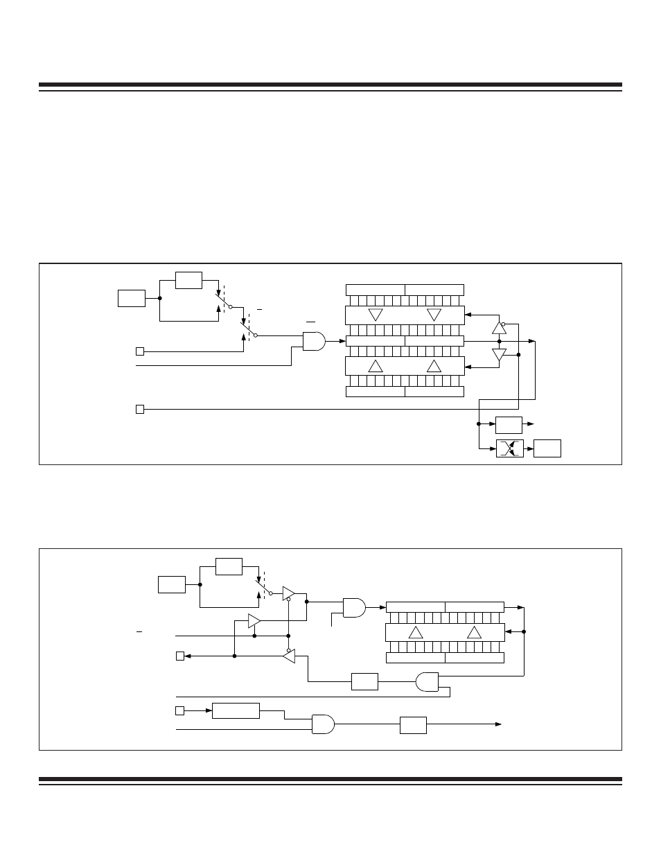
8.1.3 Timer 1 Mode: Up/Down Count with Auto-Reload
The up/down count auto-reload option is enabled by the DCEN (T1CN.4) bit. When DCEN is set to logic 1, Timer 1 counts up or down
as controlled by the state of T1EX pin. T1EX causes upward counting when a logic 1 is applied and down counting when a logic 0 is
applied. When DCEN = 0, Timer 1 only counts up.
When an upward counting overflow occurs, the value in T1CH and T1CL loads into T1H and T1L. In the down count direction, an under-
flow occurs when T1H and T1L match the values in T1CH and T1CL, respectively. When an underflow occurs, FFFFh is loaded into
T1H and T1L and counting continues.
Note that in this mode, the overflow/underflow output of the timer is provided to an edge-detection circuit as well as to the TF1 bit
(T1CN.7). This edge-detection circuit toggles the EXF1 bit (T1CN.6) on every overflow or underflow. Therefore, the EXF1 bit behaves
as a 17th bit of the counter, and may be used as such.
8-4
MAXQ Family User’s Guide
TR1 = T1CN.2
CLK
0
0
C/T1 = T1CN.1
T1M = T1MD.0
T1 PIN
DIVIDE
BY 12
TIMER 1
INTERRUPT
SYSTEM
CLOCK
T1L
T1H
15
15
T1CH
FFH
FFH
(DOWN COUNTING RELOAD VALUE)
(UP COUNTING RELOAD VALUE)
COUNT DIRECTION
(1 = UP, 0 = DOWN)
EXF1 =
T1CN.6
TF1 =
T1CN.7
T1EX PIN
1
1
T1CL
Figure 8-3. Timer/Counter 1 16-Bit Up/Down Count with Auto-Reload
TR1 =
T1CN.2
0
T1M = T1MD.0
T1 PIN
C/T1 = T1CN.1 = 0
DIVIDE
BY 12
DIVIDE
BY 2
TIMER 1
INTERRUPT
SYSTEM
CLOCK
T1L
T1H
8
8
0
T1CH
T1CL
T1OE = T1CN.5 = 1
EXEN1 = T1CN.3
T1EX PIN
EXF1 =
T1CN.6
T1 FREQUENCY OUT = SYSTEM CLOCK (2 x (65,536 – T1CH, T1CL))
ƒ
1
0
7
7
15
15
Figure 8-4. Timer 1 Clock Output Mode
8.1.4 Timer 1 Mode: Clock Output
Timer 1 can also be configured to drive a clock output on the T1 port pin, as shown in Figure 8-4. To configure Timer 1 for this mode,
it must first be set to 16-bit auto-reload timer mode (CP/RL1 = 0, C/T1 = 0). Next, the T1OE (T1CN.5) bit must be set to logic 1. TR1
Maxim Integrated