2 baud-rate generation, 1 mode 0 baud rate, 2 mode 2 baud rate – Maxim Integrated MAXQ Family User Manual
Page 109: 3 mode 1 or 3 baud rate, 4 baud-clock generator, 2 baud-rate generation -8, 1 mode 0 baud rate -8, 2 mode 2 baud rate -8, 3 mode 1 or 3 baud rate -8, 4 baud-clock generator -8
10.2 Baud-Rate Generation
Each mode of operation has a baud-rate generator associated with it. The baud-rate generation techniques are affected by certain
user options such as the Power Management Mode Enable (PMME), Serial Mode 2 (SM2) select bit, and Baud-Rate Doubler (SMOD)
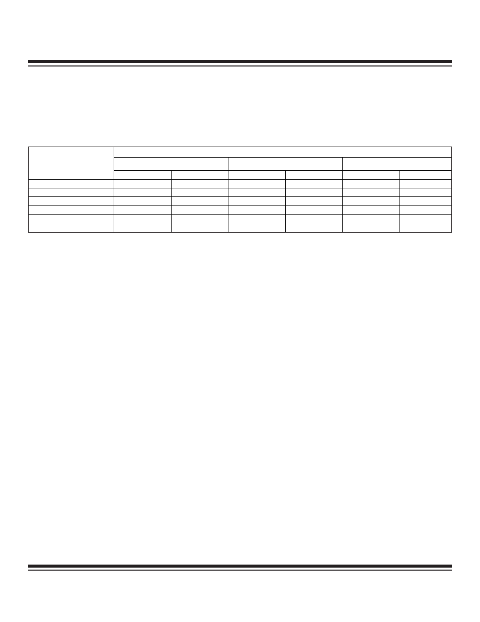
bit. Table 10-2 summarizes the effects of the various user options on the UART baud clock.
Table 10-2. UART Baud Clock Summary
10.2.1 Mode 0 Baud Rate
Baud rates for mode 0 are driven directly from the system clock source divided by either 12 or 4, with the default case being divide
by 12. The user can select the shift clock frequency using the SM2 bit in the SCON register. When SM2 is set to logic 0, the baud rate
is fixed at a divide by 12 of the system clock. When SM2 is set to logic 1, the baud rate is fixed at a divide by 4 of the system clock.
Mode 0 Baud Rate = System Clock Frequency x 3
SM2
/ 12
10.2.2 Mode 2 Baud Rate
In this asynchronous mode, baud rates are also generated from the system clock source. The user can effectively double the UART
baud clock frequency by setting the SMOD bit to a logic 1. The SMOD bit is set to a logic 0 on all resets, thus making ‘divide by 64’
the default setting. The baud rate is given by the following formula:
Mode 2 Baud Rate = System Clock Frequency x 2
SMOD
/ 64
10.2.3 Mode 1 or 3 Baud Rate
These asynchronous modes are commonly used for communication with PCs, modems, and other similar interfaces. The baud rates
are programmable using the baud clock generator in the UART module. The baud clock generator is basically a phase accumulator
that generates a baud clock as the result of phase overflow into the most significant bit of the phase shifter. This baud-clock genera-
tor is driven by the system clock or system clock divided-by-4 source (depending upon the state of the SMOD bit). The baud-clock-
generator output is always divided by 16 to generate the exact baud rate.
10.2.4 Baud-Clock Generator
The baud-clock generator is basically a phase accumulator that produces a baud clock as the result of phase overflow from the most
significant bit of the phase shift circuitry. A 16-bit Phase Register (PR) is programmable by the user to select a suitable phase value
for its baud clock. The phase value dictates the phase period of the accumulation process. The phase value is added to the current
phase accumulator value on each system clock (SMOD = 1) or every 4th system clock (SMOD = 0). The baud clock is the result of
addition overflow out of the most significant bit of the phase accumulator (bit 16). The baud-clock-generator output is always divided
by 16 to produce the exact baud rate.
The following two formulas can be used to calculate the output of the baud-clock generator and the resultant Mode 1, 3 baud rates.
Additionally, Table 10-3 gives example phase register (PR) settings needed to produce some more common baud rates at certain sys-
tem clock frequencies (assuming SMOD = 1).
Baud Clock Generator Output (BAUD) = System Clock Frequency x PR / 2
17
Baud Rate for Modes 1 and 3 = BAUD x 2
(SMOD x 2)
/ 2
6
10-8
MAXQ Family User’s Guide
BAUD CLOCK FREQUENCY
MODE 0
MODE 2
MODE 1, 3
†
SYSTEM CLOCK MODE
SM2 = 0
SM2 = 1
SMOD = 0
SMOD = 1
SMOD = 0
SMOD = 1
Divide by 1 (default)
CLK /12
CLK /4
CLK /64
CLK /32
BAUD /64
BAUD /16
Divide by 2
CLK /24
CLK /8
CLK /128
CLK /64
BAUD /64
BAUD /16
Divide by 4
CLK /48
CLK /16
CLK /256
CLK /128
BAUD /64
BAUD /16
Divide by 8
CLK /96
CLK /32
CLK /512
CLK /256
BAUD /64
BAUD /16
Power Management Mode
(Divide by 256)
CLK /3072
CLK /1024
CLK /16384
CLK /8192
BAUD /64
BAUD /16
†
The BAUD frequency is determined by the baud-clock generator.
Maxim Integrated