Rockwell Automation IASIMP Computer Numerical Control (CNC) Machining Accelerator Toolkit Quick Start User Manual
Page 69
Rockwell Automation Publication IASIMP-QS034A-EN-P - October 2012
69
FANUC CNC Configuration
Chapter 3
The CNC architecture consists of two central processing units (CPUs), one specifically for the coordinated
machine motion (CNC), and one for the machine I/O and peripheral functions (PMC).
The CNC is the machine module in this example. It consists of proprietary software from FANUC, and is a layer
that is not accessible for modifications. FANUC provides a means to interface with a CNC by using pre-defined
system data table address registers. Refer to the FANUC documentation provided with your CNC for more
information.
Within the PMC, there are application modules and device modules. The modules are described below:
•
Application Modules
– The application modules execute the machine commands and provide the more
specific application commands for the CNCs functions. These modules must be defined, edited, and
completed for your specific application prior to final commissioning on a CNC machine. To complete the
proper handshaking between the PLC and CNC for the example project, these application modules have
been programmed with timers to simulate a response. Add the custom application code as necessary to
complete the programming for the specific application in these areas.
•
Device Modules
– The device modules translate the overall machine and application commands, and
provide uniform status and diagnostics from/to the very specific EtherNet/IP device tags. This reduces
much of the non-inventive code required to control and monitor the EtherNet/IP device.
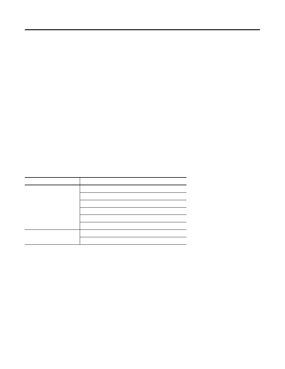
Table 2 - Preconfigured Logic Modules Used in CNC Work Cell Example
Module Type
File Names
Application
LEVEL1
LEVEL2
P0001 (OP Panel Path 1)
P0005 (Machine Sequence)
P0010 (Window Functions)
P0023 (Alarm Routine)
Device
P0015 (PLC EIP Input Routine)
P0016 (PLC EIP Output Routine)