Fault indication view – Rockwell Automation IASIMP Computer Numerical Control (CNC) Machining Accelerator Toolkit Quick Start User Manual
Page 223
Rockwell Automation Publication IASIMP-QS034A-EN-P - October 2012
223
System Application Guide
Chapter 7
Table 10 - General Status/Control Buttons
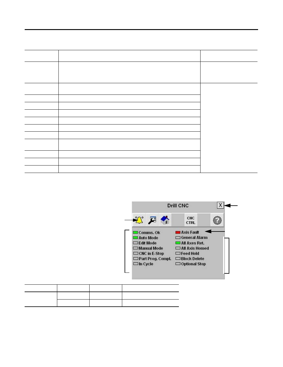
Fault Indication View
The Alarm button indicates a
CNC fault condition and
activates the fault diagnostic
views.
Table 11 - Fault Indication View
To access the detailed fault information and action displays, press the alarm button on the toolbar.
Button/Indicator
Description
Conditions Required for
Each Manual Control Button
Program/Operator
Toggles the control mode between Program and Operator mode.
Operator mode permits manual control of the drive from the faceplate. Program mode
operates the drive according to the Logix program. The active control mode is displayed on
the button.
Machine cannot be in the
STARTING or RUNNING state
Cycle Start/Cycle
Stop
Toggles the drive between the start and stop states. The active state of the drive is
displayed on the button.
Operator mode
CLR Alarms
Sends command to CNC to clear any active CNC alarms.
CLR Faults
Sends command to CNC to clear any active CNC faults.
Home
Commands the CNC to go to it's HOME position.
Block Delete
Sends the BLOCK DELETE command to the CNC.
Optional Stop
Sends the OPTIONAL STOP command to the CNC.
Feed Hold
Puts the CNC into FEED HOLD.
Unload Mch.
Sends the UNLOAD MACHINE command to the CNC, and sets commands the CNC back to
it's RETURNED position.
Gage Part
Sends the GAGE PART command to the CNC.
E. Return
Sends the EMERGENCY RETURN command to the CNC, HOMING and RETURNING the axis.
Tool Change
Sends the TOOL CHANGE command to the CNC.
Toolbar Button
Color Indicator
Description
Action
Alarm
Gray
Normal state
None
Flashing yellow
Fault
Follow fault action screen
Current Fault
Indicators
Flashing Fault
Indicator
Close
Button
General Status
Indicators
Alarm Indicator