GW Instek APS-1102A User Manual User Manual
Page 48
APS-1102A User Manual
APS-1102A
3-14
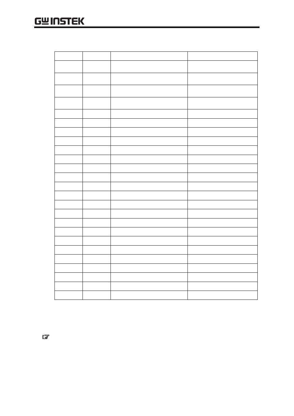
Table3-6. External Control I/O Connectors
Pin No.
I/O
Function
Remark
1
Output
Power source on/off status
0: Off
1: On
2
Output
Output on/off status
0: Off
1: On
3
Output
Limiter operation
Note
0: Off
1: On
4
Output
Software busy
0: Normal
1: Busy
5
Output
Sequence sync output 0
6
Output
Sequence sync output 1
7
Output
Undefined
8
Output
Undefined
9
GND
-
10
Input
Undefined
11
Input
Output off
Falling detection
12
Input
Output on
Falling detection
13
Input
Sequence start
Falling detection
14
Input
Sequence stop
Falling detection
15
Input
Sequence hold
Falling detection
16
Input
Sequence branch trigger 0
Falling detection
17
Input
Sequence branch trigger 1
Falling detection
18
GND
-
19
Output
+5 V
50 mA or less
20
Output
Reserved
21
Output
Reserved
22
Output
Reserved
23
Output
Reserved
24
Output
Reserved
25
Output
Reserved
Note When peak current limiter (positive), peak current limiter (negative), RMS current limiter,
or output power limiter is operated, it is recognized as a limiter operation on.
External control input and output can be used when external control has been set as enabled.
See “5.6.7 External control input enable/disable setting”.