Setting output voltage, Setting output frequency, Output initial phase settings – GW Instek APS-1102A User Manual User Manual
Page 152: 3 setting output voltage
APS-1102A User Manual
APS-1102A
5-18
5.3.3 Setting output voltage
The output voltage settings listed below can be made for the two operation modes.
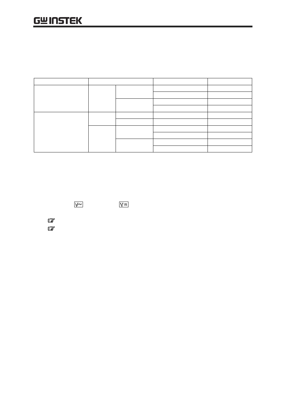
Table5-13. Output Voltage Settings
Operation Mode
Setting
Setting Range
Resolution
AC mode
(AC-INT,
AC-ADD,
AC-SYNC)
AC
voltage
100 V range
0.0 to 155.0 Vrms
0.1 Vrms
0.0 to 440.0 Vp-p
0.1 Vp-p
200 V range
0.0 to 310.0 Vrms
0.1 Vrms
0.0 to 880.0 Vp-p
0.1 Vp-p
AC+DC mode
(AC+DC-INT,
AC+DC-ADD,
AC+DC-SYNC)
DC
voltage
100 V range
220.0 to +220.0 V
0.1 V
200 V range
440.0 to +440.0 V
0.1 V
AC
voltage
100 V range
0.0 to 155.0 Vrms
0.1 Vrms
0.0 to 440.0 Vp-p
0.1 Vp-p
200 V range
0.0 to 310.0 Vrms
0.1 Vrms
0.0 to 880.0 Vp-p
0.1 Vp-p
When the selected AC voltage waveform is either SIN (sine wave) or SQU (square wave), the AC voltage
setting is made in Vrms units. When it is ARB (arbitrary waveform) 1 to 16, this setting is made in Vp-p
units.
Operation steps
Select either
“AC voltage” or
“DC voltage” in the output voltage SET menu then set a
numerical value.
S
ee “3.4.5 Setting output voltage”, for description of output voltage setting.
See also “4.1.4 Setting the output voltage”.