2 display and initial settings at power-on – GW Instek APS-1102A User Manual User Manual
Page 39
3 PANEL AND BASIC OPERATIONS
APS-1102A
3-5
3.2 Display and Initial Settings at Power-on
Display at power-on
When the power switch is set to on, a fault check is performed automatically, and when that ends
normally operation mode is set.
The settings shown on the panel are those that were shown the last time the power source was turned
off. When a newly purchased unit is turned on for the first time, the initial settings are displayed.
See “4.8 Using Memory Functions”, for description of how to read settings saved to
memory.
An error message is displayed when an abnormality has occurred. After reading the error message,
turn the power source off immediately.
See “7.2.1 Error at power-on”, for description of error messages and recommended
responses.
Initial settings
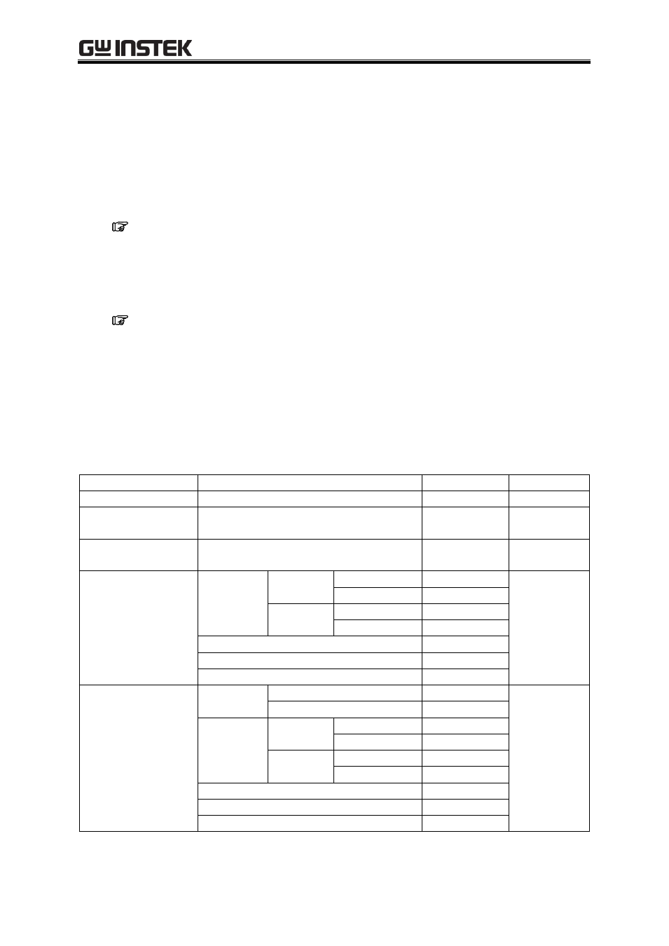
Table3-1 to Table3-3 list the initial settings for the APS-1102A. When you reset this product, the items
with a check mark in Table3-1 to Table3-3 are set to the initial setting value. Turn the output off, before
reset.
Table3-1. Settings in Memory (1/3)
Function
Setting
Initial Setting
Reset
Select output mode
Output mode
AC-INT
Select output voltage
range
Output voltage range
100 V
Select external sync
signal source
External sync signal source
LINE
AC mode output
(AC-INT,
AC-ADD,
AC-SYNC)
AC voltage
100 V range
SIN/SQU
0.0 Vrms
ARB1 to ARB16
0.0 Vp-p
200 V range
SIN/SQU
0.0 Vrms
ARB1 to ARB16
0.0 Vp-p
AC voltage frequency
50.0 Hz
Phase when the output turns on
0.0
AC voltage waveform
Sine wave (SIN)
AC+DC mode output
(AC+DC-INT,
AC+DC-ADD,
AC+DC-SYNC)
DC voltage
100 V range
0.0 V
200 V range
0.0 V
AC voltage
100 V range
SIN/SQU
0.0 Vrms
ARB1 to ARB16
0.0 Vp-p
200 V range
SIN/SQU
0.0 Vrms
ARB1 to ARB16
0.0 Vp-p
AC voltage frequency
50.0 Hz
Phase when the output turns on
0.0
AC voltage waveform
Sine wave (SIN)