5 operation principles – GW Instek APS-1102A User Manual User Manual
Page 23
1 OVERVIEW
APS-1102A
1-7
1.5 Operation Principles
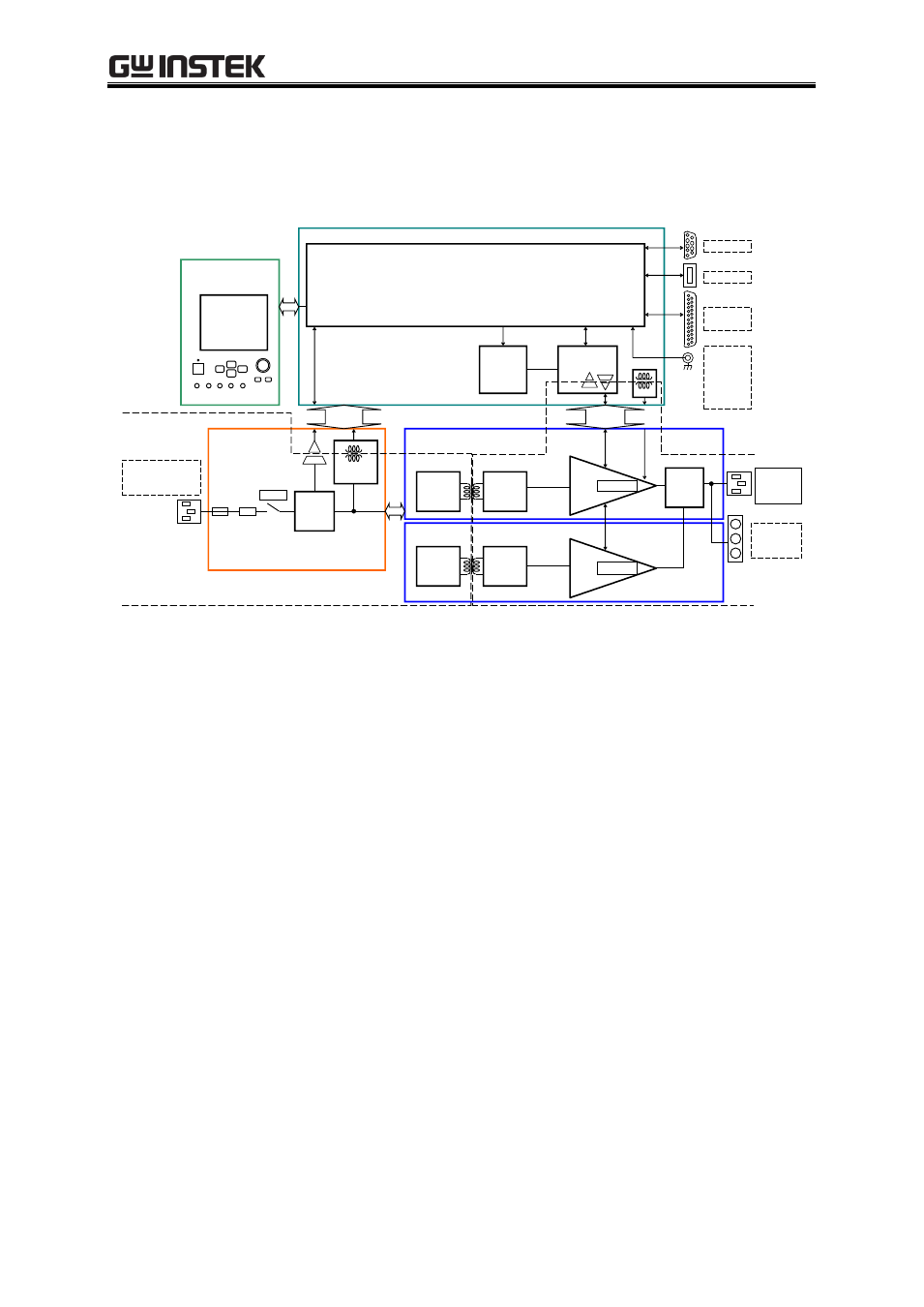
Figure 1-1 shows a block diagram of the APS-1102A.
PFC
CIRCUIT
~LINE 100V-230V
50Hz/60Hz
1.4kVA MAX
POWER
LINE
FILTER
SUB-DCPS
CIRCUIT
<1>PFC
INVERTER
ISO
CIRCUIT
(PRI)
ISO
CIRCUIT
(SEC)
<3>AMP 1
<4>AMP
INVERTER
OUTPUT
±440Vpk MAX
1kVA MAX
CONTROL
I/O
USB
EXT SIG IN
±2.2V MAX
Zin=10kΩ
EXT SYNC IN
TTL
PANEL
<2>CONTROLLER
OSC
AMP
CONTROL
SYSTEM
CONTROL
DISPLAY
POWER
AMP
PROTECT
OUTPUT
AC250V MAX
1kVA MAX
ISO
CIRCUIT
(SEC)
ISO
CIRCUIT
(PRI)
POWER
AMP
PROTECT
<3>AMP 2
RANGE
CHANGER
RS232
Figure 1-1. Block Diagram
The APS-1102A is broadly divided into four blocks.
<1> DC power source block
The DC power source block includes power factor improvement functions. The block provides DC
power sources for various devices on PCBs and for the amplifier block, while improving the power
factor of power supply input.
<2> Signal source and system control block
This block includes an internal signal source with sequence functions, and is able to provide
AC+DC output. It can also be used with added external inputs and internal signal sources. This
block also contains the user interface.
<3> Isolation block
The isolation block isolates the primary side (mains circuit) and secondary sides.
<4> Amplifier block
The amplifier block includes a protection circuit.