2 output voltage range setting – GW Instek APS-1102A User Manual User Manual
Page 151
5 MENUS
APS-1102A
5-17
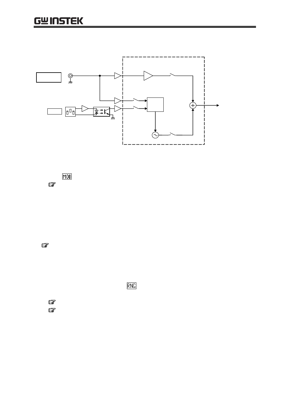
Figure 5-7 shows a block diagram of the APS-1102A signal sources.
Figure 5-7. Block Diagram of Signal Sources
Operation steps
Select
in the SET menu.
See
“3.4.2 Setting output mode”, for how to select the output mode.
5.3.2 Output voltage range setting
Select 100 V or 200 V as the output voltage range.
The output voltage range cannot be changed when output is on.
The output voltage setting, current limiter setting, etc., vary according to the output voltage range setting.
See “Table4-2. Setting Range Options for Various Output Voltage Ranges”.
Output voltage range settings are retained for each operation mode (AC and AC+DC).
Operation steps
To set the output voltage range, select
in the SET menu.
For description of output voltage range settings:
See “3.4.3 Setting output voltage range”.
See “4.1.3 Setting the output voltage range”.
PLL
To AMP CONTROL
EXT INPUT GAIN
EXT
ADD
INT
ADD
SYNC
INT OSC
EXT SIG IN
EXT SYNC
EXT
LINE
LINE
SYNC
SYSTEM CONTROL
- GDB-03 (99 pages)
- GLA-1000 Series User Manual (111 pages)
- GLA-1000 Series Quick start guide (20 pages)
- GOS-630FC (20 pages)
- GOS-635G (36 pages)
- GOS-6000 Series (27 pages)
- GOS-6103C (30 pages)
- GOS-6100 Series (30 pages)
- GRS-6000A Series (51 pages)
- GDS-122 Installation Guide (4 pages)
- GDS-122 User Manual (52 pages)
- GDS-2000A series CAN/LIN bus User Manual (18 pages)
- GDS-2000A series Quick start guide for DS2-FGN (6 pages)
- GDS-2000A series Freewave User Manual (26 pages)
- GDS-2000A series Quick start guide for Logic analyzer option (18 pages)
- GDS-2000A series Quick start quide for DS2-LAN (2 pages)
- GDS-2000A series Option User Manual (80 pages)
- GDS-2000A series User Manual (261 pages)
- GDS-2000A series Programming Manual (272 pages)
- GDS-2000A series Single sheet for LA Quick start guide (2 pages)
- GBS-1000 Series Programming Manual (88 pages)
- GBS-1000 Series User Manual (187 pages)
- GDS-1000-U Series firmware upgrade (1 page)
- GDS-1000-U Series Programming Manual (70 pages)
- GDS-1000-U Series Quick start guide (2 pages)
- GDS-1000-U Series User Manual (133 pages)
- GDS-1000A-U Series Programming Manual (88 pages)
- GDS-1000A-U Series Quick start guide (2 pages)
- GDS-1000A-U Series User Manual (148 pages)
- GDS-3000 Series GCP-530/1030 current probe User Manual (40 pages)
- GDS-3000 Series GDP-025/050/100 differential probe User Manual (21 pages)
- GDS-3000 Series DS3-PWR Power analysis manual (37 pages)
- GDS-3000 Series User Manual (209 pages)
- GDS-3000 Series Programming Manual (103 pages)
- GDS-3000 Series DS3-SBD Serial Bus decode (29 pages)
- GDS-3000 Series GKT-100 deskew fixture User Manual (1 page)
- GDS-3000 Series GUG-001, GPIB to USB adapter User Manual (15 pages)
- GDS-300 Series User Manual (188 pages)
- GDS-300 Series Programming Manual (139 pages)
- GDS-300 Series Quick start guide (21 pages)
- GRF-3300 Series Student Manual (26 pages)
- GRF-3300 Series Teacher Manual (26 pages)
- GRF-1300A (124 pages)
- GSP-810 User Manual (40 pages)
- GSP-810 Software Manual (3 pages)