Table 2.6 differential mode – Avago Technologies LSI53C825AE User Manual
Page 52
2-28
Functional Description
2.4.9.1 Differential Mode
In differential mode, the SDIR[15:0], SDIRP[1:0], IGS, TGS, RSTDIR,
BSYDIR, and SELDIR signals control the direction of external differential
pair transceivers. The LSI53C825A is placed in differential mode by
setting the DIF bit, bit 5 of the
register (0x4E).
Setting this bit 3-states the BSY/, SEL/, and RST/ pads so they can be
used as pure input pins. In addition to the standard SCSI lines, the
following signals defined in
are used during differential
operation by the LSI53C825A.
See
for an example differential wiring diagram, in which the
LSI53C825A is connected to the TI 75LBC976 differential transceiver.
The recommended value of the pull-up resistor on the REQ/, ACK/,
MSG/, C/D/, I/O/, ATN/, SD[7:0]/, and SDP0/ lines is 680
Ω
when the
Active Negation portion of LSI Logic TolerANT technology is not enabled.
When TolerANT technology is enabled, the recommended resistor value
on the REQ/, ACK/, SD[7:0]/, and SDP0/ signals is 1.5 k
Ω
. The electrical
characteristics of these pins change when TolerANT is enabled,
permitting a higher resistor value.
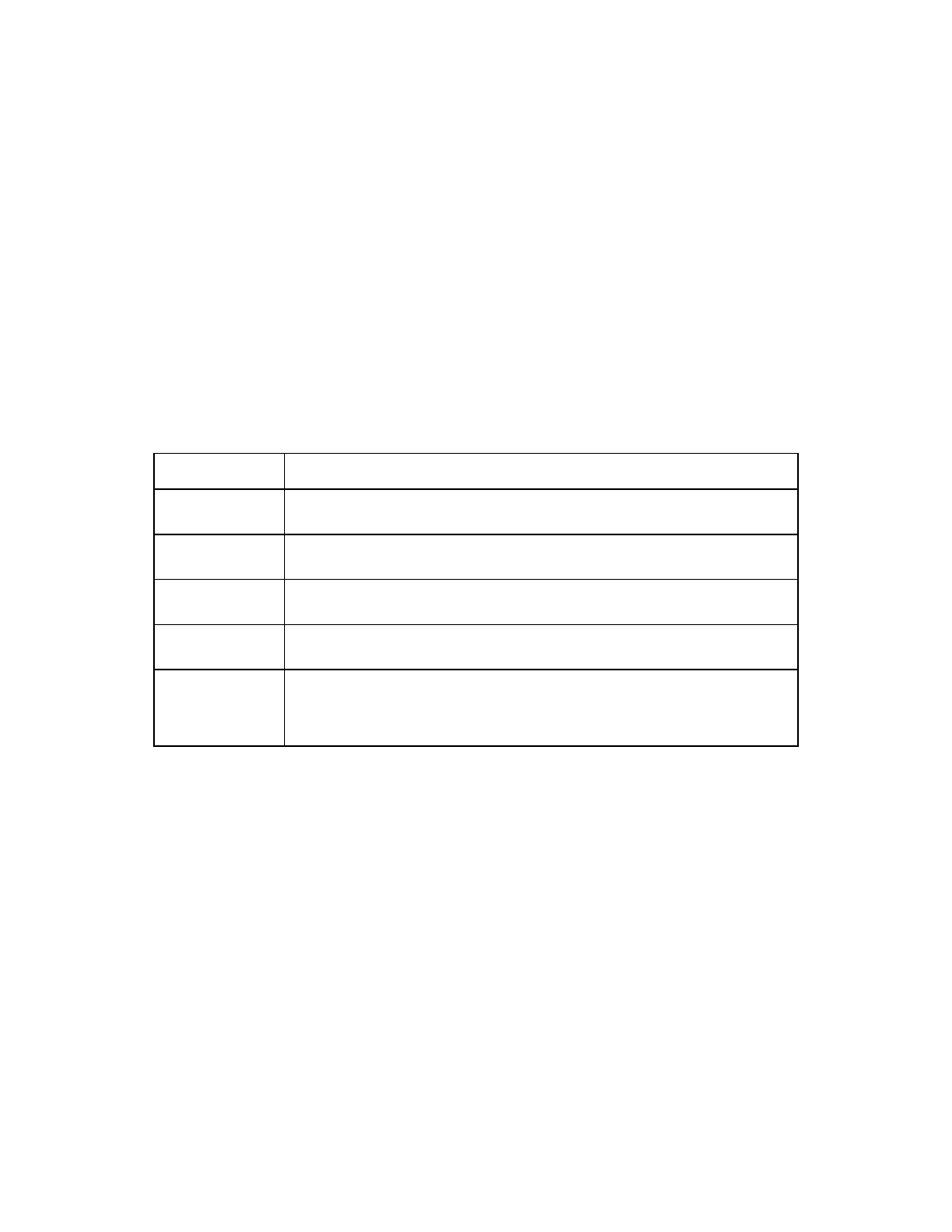
Table 2.6
Differential Mode
Signal
Function
BSYDIR, SELDIR,
RSTDIR
Active HIGH signals used to enable the differential drivers as outputs for SCSI
signals BSY/, SEL/, and RST/, respectively.
SDIR[15:0],
SDIRP[1:0]
Active HIGH signals used to control direction of the differential drivers for SCSI
data and parity lines, respectively.
IGS
Active HIGH signal used to control direction of the differential driver for initiator
group signals ATN/ and ACK/.
TGS
Active HIGH signal used to control direction of the differential drivers for target
group signals MSG/, C/D/, I/O/, and REQ/.
DIFFSENS
Input to the LSI53C825A used to detect the presence of a SE device on a
differential system. If a logical zero is detected on this pin, then it is assumed
that an SE device is on the bus and all SCSI outputs will be 3-stated to avoid
damage to the transceiver.