Table 2.2 external memory support – Avago Technologies LSI53C825AE User Manual
Page 40
2-16
Functional Description
To use one of the configurations mentioned above in a host adapter
board design, put 4.7 k
Ω
pull-down resistors on the MAD pins
corresponding to the available memory space. For example, to connect
to a 32 Kbyte external ROM, use pull-downs on MAD3 and MAD2. If the
external memory interface is not used, then no external resistors are
necessary since there are internal pull-ups on the MAD bus. The internal
pull-up resistors are disabled when external pull-down resistors are
detected, to reduce current drain.
The LSI53C825A allows the system to determine the size of the available
external memory using the
register in
PCI configuration space. For more information on how this works, refer
to the PCI specification or the
register
description in
Chapter 3, “Signal Descriptions.”
MAD0 is the slow ROM pin. When pulled down, it enables two extra clock
cycles of data access time to allow use of slower memory devices. The
external memory interface also supports updates to flash memory. The
12 V power supply for flash memory, V
PP
, is enabled and disabled with
the GPIO4 pin and the GPIO4 control bit. For more information on the
GPIO4 pin, refer to
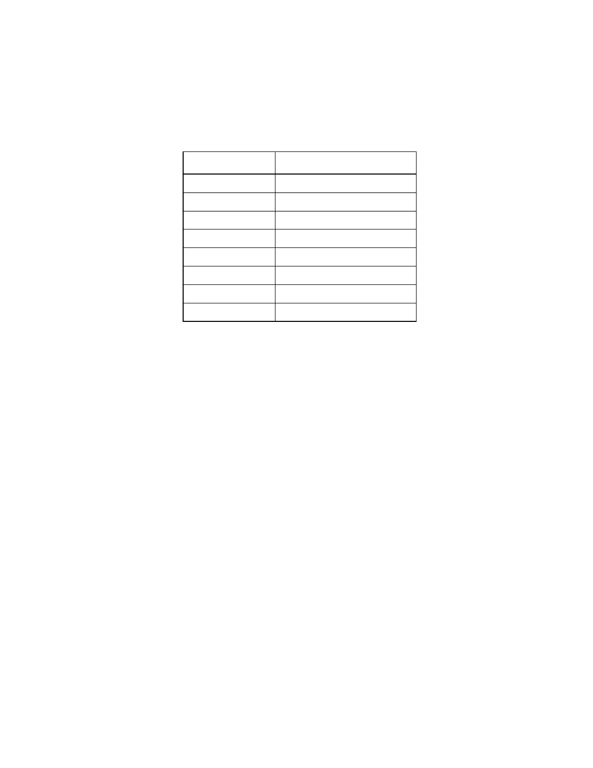
Table 2.2
External Memory Support
MAD[3:1]
Available Memory Space
000
16 Kbytes
001
32 Kbytes
010
64 Kbytes
011
128 Kbytes
100
256 Kbytes
101
512 Kbytes
110
1024 Kbytes
111
No external memory present