Compensating workpiece misalignment -12 – HEIDENHAIN TNC 407 (280 580) ISO Programming User Manual
Page 73
TNC 426/TNC 425/TNC 415 B/TNC 407
2 - 1 2
2
Manual Operation and Setup
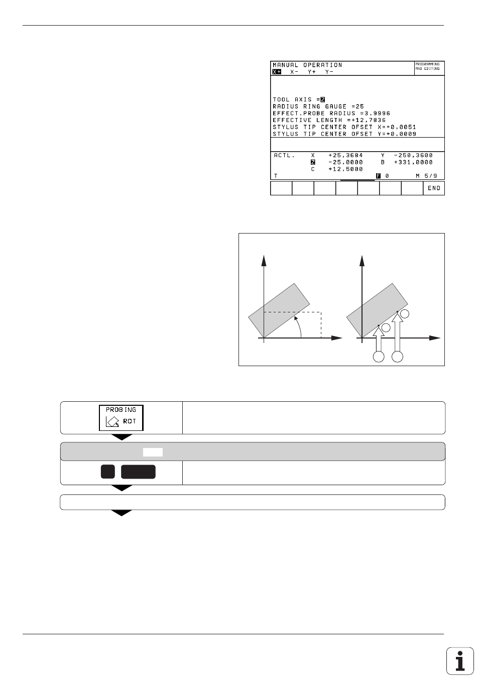
Fig. 2.11:
Menu for touch probe radius and center
misalignment
Compensating workpiece misalignment
The TNC electronically compensates workpiece
misalignment by computing a "basic rotation".
You set the rotation angle to the desired angle with
respect to the reference axis in the working plane
(see page 1-13).
Press the PROBING ROT soft key.
ROTATION ANGLE =
Enter the nominal value of the rotation angle.
Move the ball tip
(A) to a starting position near the first touch point (1).
E 4
Displaying calibration values
The effective length and radius, and the center
misalignment of the 3D touch probe are stored in
the TNC for use when the touch probe is needed
again. You can display the values on the screen
with the soft keys CAL L and CAL R.
0
e.g.
ENT
.
.
.
H
A
B
2
1
Fig. 2.12:
Basic rotation of a workpiece; probing procedure for
compensation
(right)
. The broken line is the nominal
position, the angle
H
is being compensated.