3d touch probes -9, 4 3d touch probes – HEIDENHAIN TNC 407 (280 580) ISO Programming User Manual
Page 70
TNC 426/TNC 425/TNC 415 B/TNC 407
2 - 9
2
Manual Operation and Setup
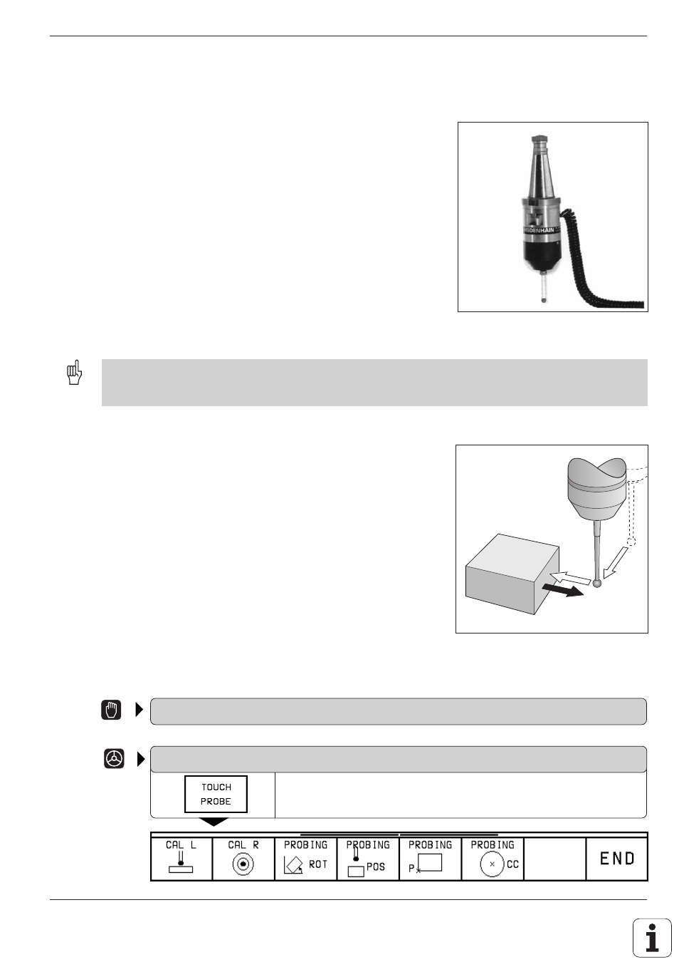
Fig. 2.8:
Feed rates during probing
Fig. 2.7:
3D touch probe model TS 120
F
max
F
F
2.4 3D Touch Probes
3D Touch probe applications
Your TNC supports a HEIDENHAIN 3D touch probe.
Typical applications for touch probes:
• Compensating misaligned workpieces (basic
rotation)
• Datum setting
• Measuring:
- lengths and workpiece positions
- angles
- radii
- circle centers
• Measurements during program run
• Digitizing 3D surfaces
• The TNC must be specially prepared by the machine manufacturerer for the use of a 3D touch probe.
• If you wish to make measurements during program run, ensure that the tool data (length, radius, axis) are taken
After you press the machine START button, the touch probe begins
executing the selected probing function. The machine tool builder sets the
feed rate F at which the probe approaches the workpiece (MP6120).
When the touch probe contacts the workpiece, it
• transmits a signal to the TNC (the coordinates of the probed position
are stored),
• stops moving, and
• returns to its starting position at rapid traverse.
If the stylus is not deflected within the distance defined
in MP 6130, the TNC displays an error message.
To select the touch probe functions:
MANUAL OPERATION
or
ELECTRONIC HANDWHEEL
Select the touch probe functions.