Α? α – HEIDENHAIN TNC 407 (280 580) ISO Programming User Manual
Page 212

7-23
TNC 426/TNC 425/TNC 415 B/TNC 407
7
Programming with Q Parameters
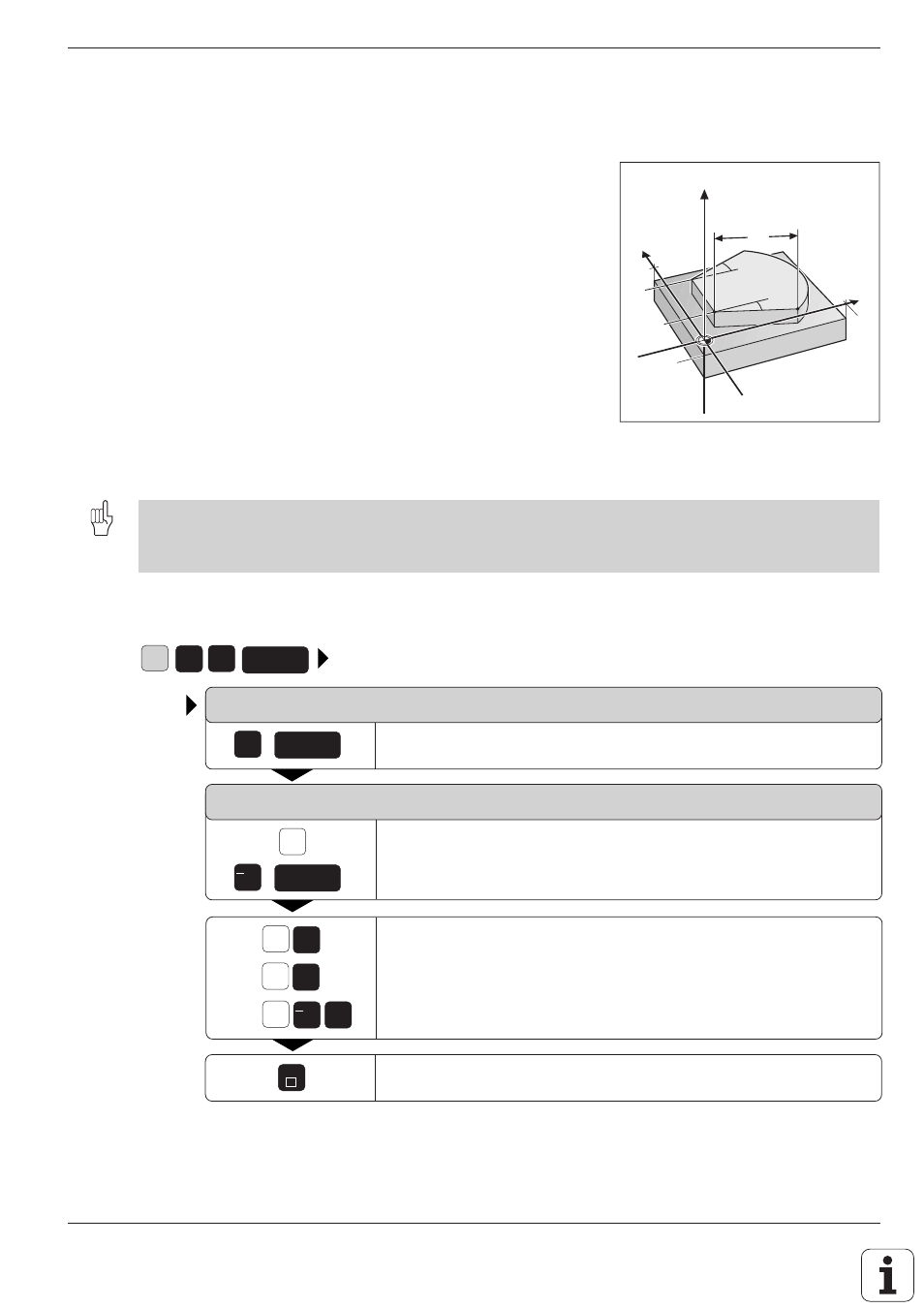
Fig. 7.4:
Dimensions to be measured
G
5
5
ENT
X
END
X
Y
Z
0
5
+/
5
+/
ENT
5
ENT
100
–10
100
α
?
α
?
Y
X
Z
L?
7.8 Measuring with the 3D Touch Probe During Program Run
The 3D touch probe can measure positions on the workpiece while the
program is being run.
Applications:
• Measuring differences in the height of cast surfaces
• Tolerance checking during machining
To program the use of a touch probe, press the TOUCH PROBE key. You
pre-position the probe to automatically probe the desired position. The
coordinate measured for the probe point is stored under a Q parameter.
The TNC interrupts the probing process if the stylus is not deflected within
a certain distance (selectable via MP6130).
Upon contact, the position coordinates of the probe are stored in the
parameters Q115 to Q119. The stylus length and radius are not included in
these values.
• Pre-position the probe manually to avoid a collision when the programmed pre-positioning point is approached.
• Use the tool data (length, radius, axis) either from the calibrated data or from the last TOOL CALL block.
Selection is made with machine parameter MP 7411 (see page 11-13).
To program the use of a touch probe:
PARAMETER NUMBER FOR RESULT ?
Enter the number of the Q parameter to which the coordinate should
be assigned, for example Q5.
PROBING AXIS/PROBING DIRECTION ?
Enter the probing axis for the coordinate, for example X.
Select and confirm the probing direction.
Enter all coordinates for the pre-positioning point values,
for example X = 5 mm, Y = 0, Z = –5 mm.
Conclude input.
Resulting NC block: G55 P01 Q5 P02 X– X+5 Y+0 Z–5 *
