Path contours – polar coordinates -28, 5 path contours – polar coordinates – HEIDENHAIN TNC 407 (280 580) ISO Programming User Manual
Page 161

TNC 426/TNC 425/TNC 415 B/TNC 407
5 - 2 8
5
Programming Tool Movements
G
1
0
R
5
3
H
0
END
X
Y
H
R
J
I
G91 H
G91 H
G91 H
G91 H
X
Y
Pol
J
I
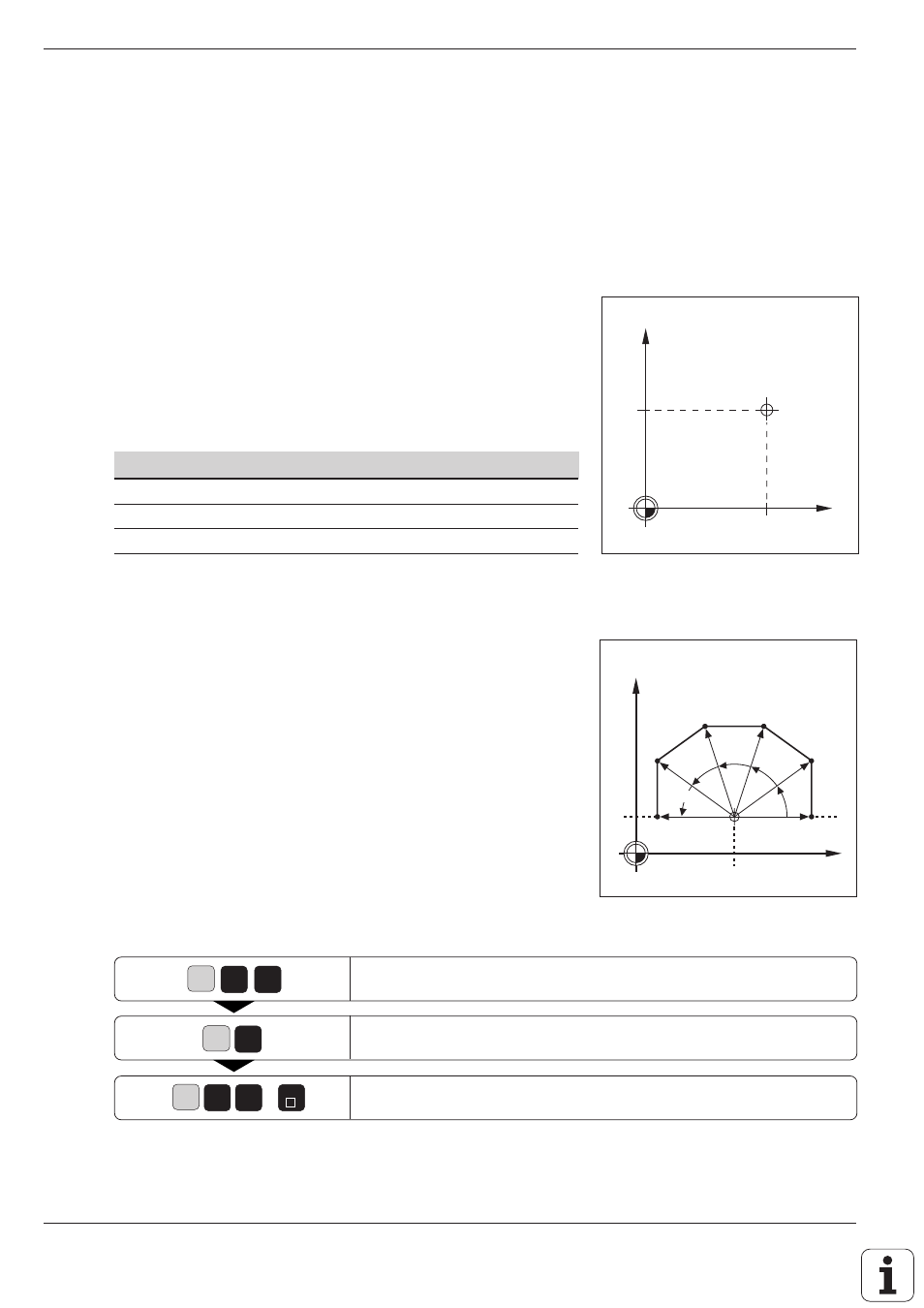
Fig. 5.37:
Contour consisting of straight
lines with polar coordinates
Fig. 5.36:
The pole is the same as a circle
center
5.5 Path Contours – Polar Coordinates
Polar coordinates are useful with:
• Positions on circular arcs
• Workpiece drawing dimensions in degrees
Polar coordinates are explained in detail in the
section “Fundamentals of NC” (page 1-12).
Polar coordinate origin: Pole I, J, K
The pole can be defined anywhere in the program before blocks
containing polar coordinates. Similar to a circle center, the pole is defined
in an I, J, K block using its coordinates in the Cartesian coordinate
system. The pole remains in effect until a new pole is defined. The
designation of the pole depends on the working plane:
Working plane
Pole
X Y
I, J
Y Z
J, K
Z X
K, J
G10: Straight line with rapid traverse
G11: Straight line with feed rate F …
• Values from –360° to +360° are permissible for the angle H
• The sign of H depends on the angle reference axis:
Angle from angle reference axis to R is counterclockwise: H>0
Angle from angle reference axis to R is clockwise: H<0
Straight line in polar coordinates with rapid traverse.
Enter radius R from pole to end point of line (here, R = 5 mm).
Enter angle H from angle reference axis to R (here, H = 30°).
Resulting NC block: G10 R5 H30 *
