Contour data (g120) -32, Yx z – HEIDENHAIN TNC 407 (280 580) ISO Programming User Manual
Page 252

8-32
8
Cycles
TNC 426/TNC 425/TNC 415 B/TNC 407
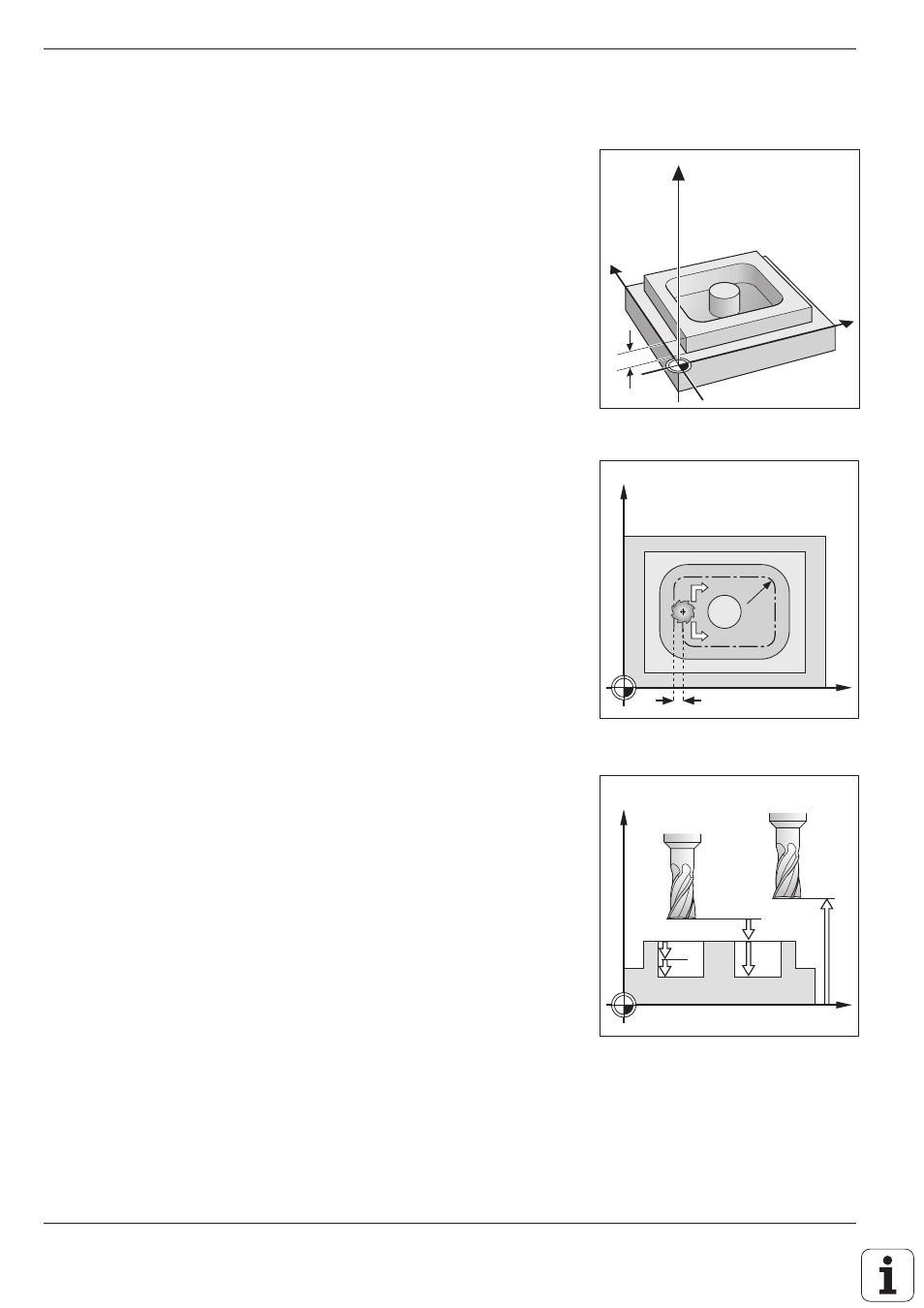
Fig. 8.37:
Direction of rotation Q9 and
stepover factor k
Fig. 8.38:
Distance and infeed parameters
Fig. 8.36: Workpiece surface coordinate Q5
Y
X
Z
Q5
X
Y
k
Q9=–1
Q9=+1
Q8
X
Z
Q1
Q6
Q10
Q7
CONTOUR DATA (G120)
Application
Machining data for the subprograms describing the subcontours are
entered in Cycle G120. These data are valid for Cycles G121 to G124.
Input data
• MILLING DEPTH Q1
Distance between workpiece surface and pocket floor. The algebraic
sign determines the working direction (negative sign means negative
working direction).
• PATH OVERLAP FACTOR Q2
Q2 * tool radius = stepover factor
k
• ALLOWANCE FOR SIDE Q3
Finishing allowance in the working plane
• ALLOWANCE FOR FLOOR Q4
Finishing allowance in the tool axis
• WORKPIECE SURFACE COORDINATE Q5
Absolute coordinate of the workpiece surface referenced to the work-
piece datum
• SETUP CLEARANCE Q6
Distance between the tool tip and the workpiece surface
• CLEARANCE HEIGHT Q7
Absolute height at which the tool cannot collide with the workpiece (for
intermediate positioning and retraction at the end of the cycle).
• INSIDE CORNER RADIUS Q8
Inside “corner” rounding radius
• DIRECTION OF ROTATION Q9
Direction of rotation for pockets:
Clockwise (Q9 = –1)
up-cut milling for pocket and island
Counterclockwise (Q9 = +1)
climb milling for pocket and island
Activation
G120 becomes effective immediately upon definition.
The machining parameters can be checked during a program interruption
and overwritten if required.
If the SL cycles are used in Q parameter programs, the cycle parameters
Q1 to Q17 cannot be used as program parameters.
