HEIDENHAIN TNC 407 (280 580) ISO Programming User Manual
Page 175
TNC 426/TNC 425/TNC 415 B/TNC 407
5 - 4 2
5
Programming Tool Movements
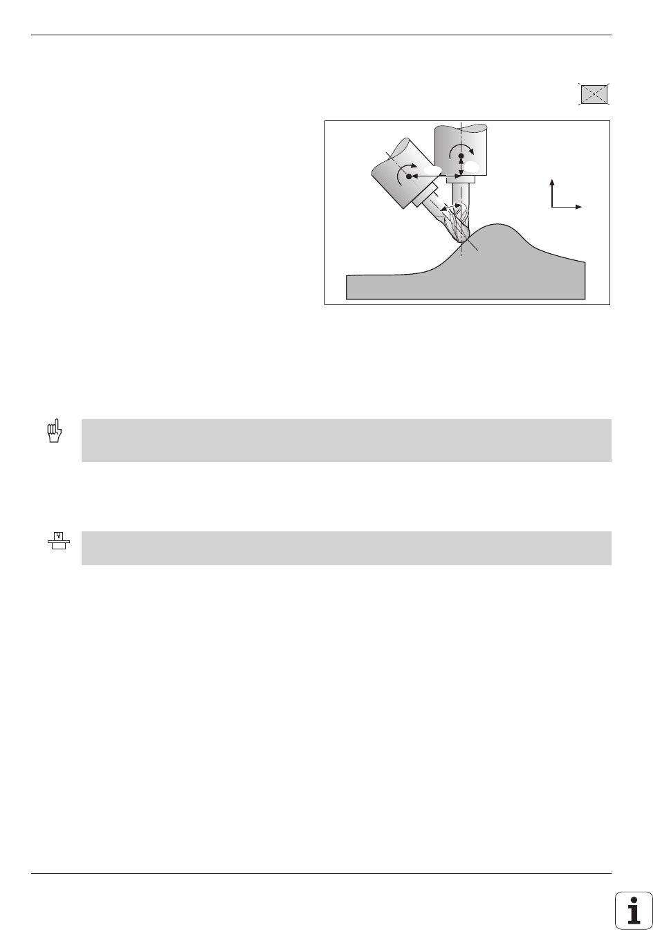
Fig. 5.51:
Offset of the tool datum for tilting the tool
M Functions for Contouring Behavior
B
dz
Z
X
B
dx
dB
The machine geometry must be defined by the machine manufacturer in machine parameters MP7510 and
following.
Automatic compensation of machine geometry when working with tilted axes: M114
Standard behavior – without M114
The TNC moves the tool to the positions given in
the part program. The tool offset resulting from a
tilted axis and the machine geometry must be
calculated by a postprocessor.
Automatic compensation of machine
geometry – with M114
The TNC compensates the tool offset resulting
from positioning with tilted axes (such as dx and dz
in Fig. 5.51). It calculates a 3D length compensa-
tion. The radius compensation must be calculated
by a CAD system or by a postprocessor. A
programmed radius compensation (RL or RR)
results in the error message ILLEGAL NC BLOCK.
Thus if you write the NC program with a
postprocessor, the machine geometry does not
have to be calculated.
If the tool length compensation is calculated by the
TNC, the programmed feed rate refers to the point
of the tool; otherwise, it refers to the tool datum.
If you are working with a swivel head under program control, you can interrupt program run and change the position
of the tilt axis (for example, with the electronic handwheel.) Use the RESTORE POS AT N function (block scan, see
page 3-8) to return to the point of interruption. The TNC automatically calculates the new tilt axis position.
Cancelling
M114 is cancelled by M115 or by a N99999 block.
407