Contour milling (g58/g59) -28 – HEIDENHAIN TNC 407 (280 580) ISO Programming User Manual
Page 248

8-28
8
Cycles
TNC 426/TNC 425/TNC 415 B/TNC 407
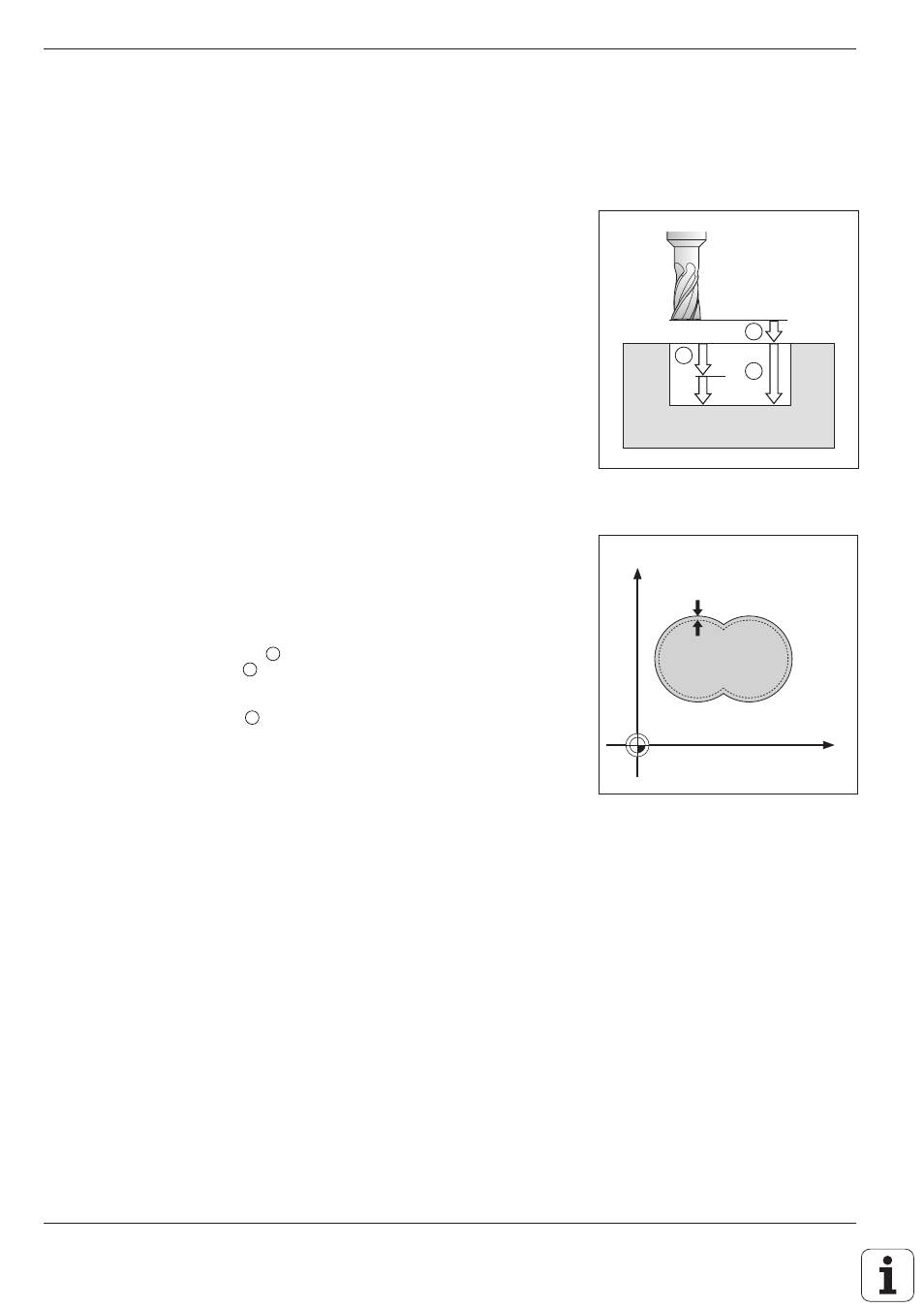
Fig. 8.32: Finishing allowance
Fig. 8.31:
Infeeds and distances for
CONTOUR MILLING
A
B
C
Y
X
D
CONTOUR MILLING (G58/G59)
The CONTOUR MILLING cycles are used to finish-mill the contour pocket.
The cycles can also be used generally for milling contours.
Sequence
• The tool is positioned at setup clearance over the first starting point.
• Moving at the programmed feed rate, the tool then penetrates to the
first pecking depth.
• Upon reaching the first pecking depth, the tool mills the first contour at
the programmed feed rate in the specified direction of rotation.
• At the infeed point, the control advances the tool to the next pecking
depth.
This process is repeated until the programmed milling depth is reached.
The remaining subcontours are milled in the same manner.
Required tool
The cycle requires a center-cut end mill (ISO 1641).
Direction of rotation during contour milling
Clockwise: G58
• For M3: up-cut milling for pocket and island
Counterclockwise: G59
• For M3: climb milling for pocket and island
Input data
• SETUP CLEARANCE
A
• MILLING DEPTH
B
The algebraic sign determines the working direction (negative sign
means negative working direction).
• PECKING DEPTH
C
• FEED RATE FOR PECKING:
Traversing speed of the tool during penetration
• FEED RATE:
Traversing speed of the tool in the machining plane
