HEIDENHAIN TNC 407 (280 580) ISO Programming User Manual
Page 188

TNC 426/TNC 425/TNC 415 B/TNC 407
6-10
6
Subprograms and Program Section Repeats
Z
X
–3
–15
–20
100
20
20
15
75
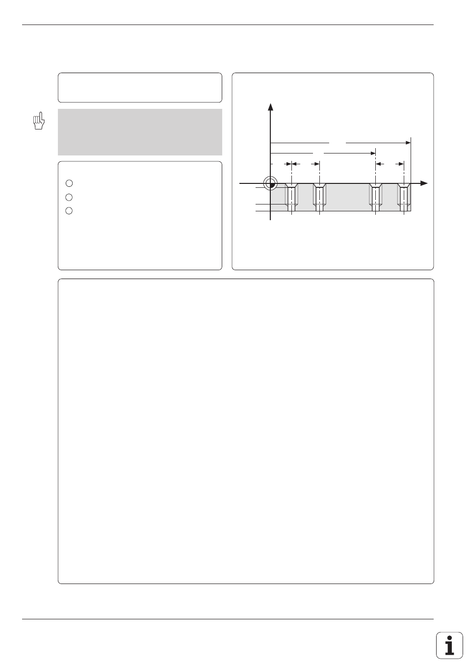
Example for exercise: Three groups of four holes (see page 6-4) with three different tools
Machining sequence:
Countersinking – Drilling – Tapping
Machining data is entered in cycle G83: PECK
DRILLING (see page 8-4) and cycle G84:
TAPPING (see page 8-6). The tool moves to the
hole groups in a subprogram, while the machin-
ing is performed in a second subprogram.
Coordinates of the first hole in each group:
1
X = 15 mm
Y = 10 mm
2
X = 45 mm
Y = 60 mm
3
X = 75 mm
Y = 10 mm
Hole spacing:
IX = 20 mm
IY = 20 mm
Hole data:
Countersinking
ZC =
3 mm
Ø = 7 mm
Drilling
ZD = 15 mm
Ø = 5 mm
Tapping
ZT = 10 mm
Ø = 6 mm
Part program
%S610I G71 * ............................................................ Start program
N10 G30 G17 X+0 Y+0 Z–20 * .................................. Define bank form
N20 G31 G90 X+100 Y+100 Z+0 *
N30 G99 T25 L+0 R+2.5 * ......................................... Tool definition for pecking
N40 G99 T30 L+0 R+3 * ............................................ Tool definition for countersinking
N50 G99 T35 L+0 R+3.5 * ......................................... Tool definition for tapping
N60 T35 G17 S3000 * ................................................ Tool call for countersinking
N70 G83 P01 –2 P02 –3 P03 –3 P04 0
P05 100 * ................................................................... Cycle definition pecking
N80 L1,0 * ................................................................. Call subprogram 1
N90 T25 G17 S2500 * ................................................ Tool call for pecking
N100 G83 P01 –2 P02 –25 P03 –10 P04 0
P05 150 * ................................................................... Cycle definition pecking
N110 L1,0 * ............................................................... Call subprogram 1
N120 T30 G17 S100 * ................................................ Tool call for tapping
N130 G84 P01 –2 P02 –15 P03 0.1 P04 100 * ........ Cycle definition tapping
N140 L1,0 * ............................................................... Call subprogram 1
N150 Z+100 M02 * .................................................... Retract in the infeed axis; end of main program
N160 G98 L1 * ........................................................... Start subprogram 1
N170 G00 G40 G90 X+15 Y+10 M03 * ..................... Move to hole group 1
N180 Z+2 * ................................................................ Pre-position in the infeed axis
N190 L2,0 * ............................................................... Call subprogram 2
N200 X+45 Y+60 * .................................................... Move to hole group 2
N210 L2,0 * ............................................................... Call subprogram 2
N220 X+75 Y+10 * .................................................... Move to hole group 3
N230 L2,0 * ............................................................... Call subprogram 2
N240 G98 L0 * ........................................................... End of subprogram 1
N250 G98 L2 * ........................................................... Start of subprogram 2
N260 G79 *
N270 G91 X+20 M99 * .............................................. Drill holes with currently active cycle
N280 Y+20 M99 *
N290 X–20 G90 M99 *
N300 G98 L0 * ........................................................... End of subprogram 2
N99999 %S610I G71 *
