HEIDENHAIN TNC 407 (280 580) ISO Programming User Manual
Page 138

5 - 5
TNC 426/TNC 425/TNC 415 B/TNC 407
5
Programming Tool Movements
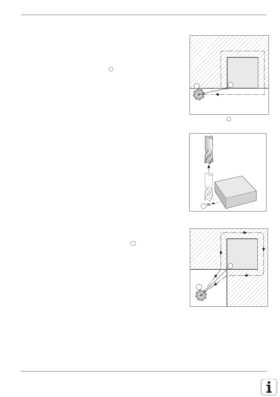
Fig. 5.8:
Common starting and end point
Fig. 5.7 :
Retract spindle axis separately
Contour Approach and Departure
E
Fig. 5.6 :
End point
E
for machining
A
SE
G40
A
E
G40
End point
Similar requirements hold for the end point:
• Can be approached without collision
• Near the last contour point
• Avoids tool damage
The ideal location for the end point
E
is again in the extension of the tool
path outside of the shaded area. It is approached without radius
compensation.
Departure from an end point in the spindle axis
The spindle axis is moved separately.
Example: G00 G40
X ... Y ...
Approach end point
Z+50
Retract tool
Common starting and end point
Outside of the shaded areas in the illustrations, it is possible to define a
single point as both the starting and end point
SE
.
The ideal location for the starting and end point is exactly between the
extensions of the tool paths for machining the first and last contour
elements.
A common starting and end point is approached without radius
compensation.
