Contour approach and departure -4, Starting point and end point -4, 2 contour approach and departure – HEIDENHAIN TNC 407 (280 580) ISO Programming User Manual
Page 137

TNC 426/TNC 425/TNC 415 B/TNC 407
5 - 4
5
Programming Tool Movements
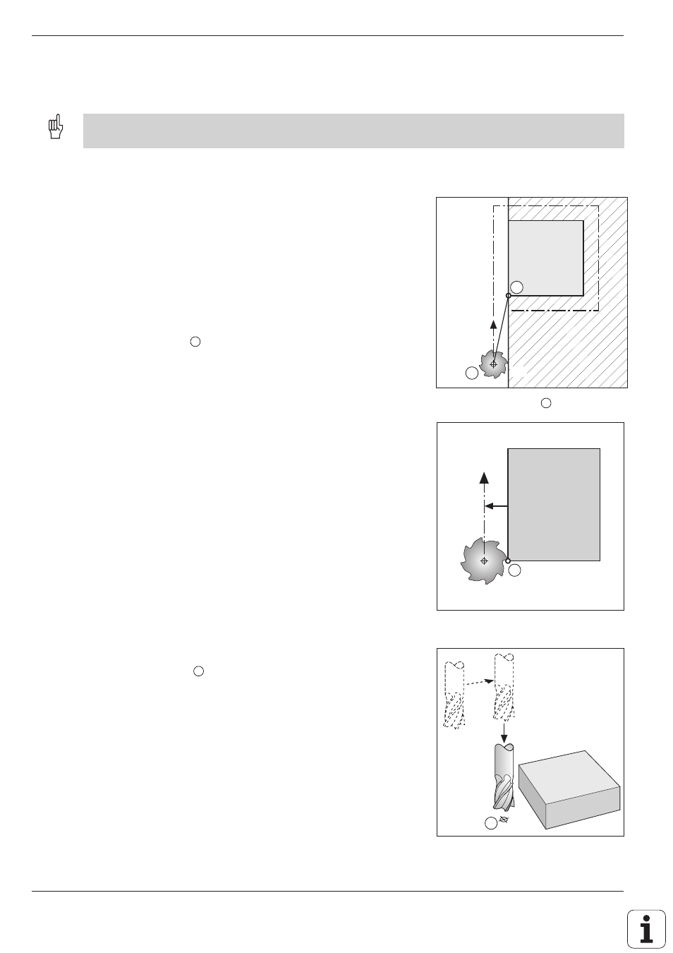
Fig. 5.4 :
First contour point for machining
Fig. 5.5 :
Separate movement of the spindle
when there is danger of collision
Fig. 5.3 :
Starting point
S
of machining
A
G41
5.2 Contour Approach and Departure
A convenient way to approach or depart the workpiece is on an arc which is tangential to the contour. This is carried
out with the approach/departure function G26 (see page 5-6).
Starting point and end point
Starting point
From the starting point, the tool moves to the first contour point.
The starting point is programmed without radius compensation.
The starting point must be:
• Approachable without collision
• Near the first contour point
• Located in relation to the workpiece such that no contour damage
occurs when the contour is approached.
If the starting point is located within the shaded area of fig. 5.4, the
contour will be damaged when the first contour point is approached. The
optimum starting point
S
is located in the extension of the tool path for
machining the first contour.
First contour point
Machining begins at the first contour point. The tool moves to this point
with radius compensation.
Approaching the starting point in the spindle axis
When the starting point
S
is approached, the spindle axis is moved to
working depth.
If there is danger of collision, approach the starting point in the spindle axis
separately.
Example:
G00 G40
X ... Y ...
Positioning X/Y
Z–10
Positioning Z
S
A
G40
S
