Altera Video and Image Processing Suite User Manual
Page 99
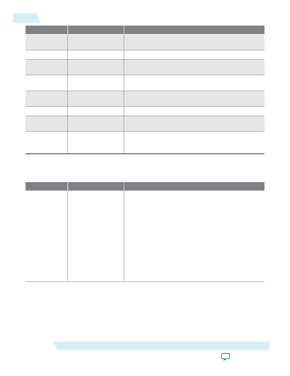
Address
Register
Description
9
F1 Total Line Count
The detected line count of the video streams F1 field including
blanking.
10
Standard
The contents of the
vid_std
signal.
11
SOF Sample
Start of frame line register. The line upon which the SOF
occurs measured from the rising edge of the F0 vertical sync.
12
SOF Line
SOF line register. The line upon which the SOF occurs
measured from the rising edge of the F0 vertical sync.
13
Refclk Divider
Number of cycles of
vid_clk
(
refclk
) before
refclk_div
signal triggers.
14
Reserved
Reserved for future use.
15
Ancillary Packet
Start of the ancillary packets that have been extracted from the
incoming video.
15 + Depth of
ancillary
memory
End of the ancillary packets that have been extracted from the
incoming video.
Table 4-22: Clocked Video Output Registers
The rows in the table are repeated in ascending order for each video mode. All of the ModeN registers are write
only.
Address
Register
Description
0
Control
• Bit 0 of this register is the
Go
bit:
• Setting this bit to 1 causes the CVO IP core start video
data output.
• Bits 3, 2, and 1 of the
Control
register are the interrupt
enables:
• Setting bit 1 to 1, enables the status update interrupt.
• Setting bit 2 to 1, enables the locked interrupt.
• Setting bit 3 to 1, enables the synchronization outputs
(
vid_sof
,
vid_sof_locked
,
vcoclk_div
).
• When bit 3 is set to 1, setting bit 4 to 1, enables frame
locking. The CVO IP core attempts to align its
vid_sof
signal to the
sof
signal from the CVI IP core.
4-40
Clocked Video Interface Control Registers
UG-VIPSUITE
2015.05.04
Altera Corporation
Clocked Video Interface IP Cores