Frame reader parameter settings, Frame reader signals, Frame reader parameter settings -3 – Altera Video and Image Processing Suite User Manual
Page 194: Frame reader signals -3
core, the Frame Reader IP core also has an interrupt that fires once per video data packet output, which is
the frame completed interrupt.
Frame Reader Parameter Settings
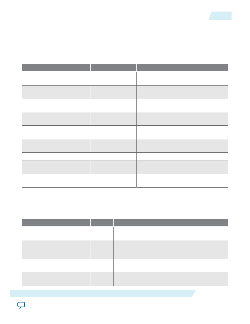
Table 13-1: Frame Reader Parameter Settings
Parameter
Value
Description
Bits per pixel per color plane
4–20, Default = 8
Select the number of bits per pixel (per color
plane).
Number of color planes in
parallel
1–4, Default = 3
Select the number of color planes that are
sent in parallel.
Number of color planes in
sequence
1–3, Default = 1
Select the number of color planes that are
sent in sequence.
Maximum image width
32–2600, Default = 640 Specify the maximum image or video frame
width in pixels.
Maximum image height
32–2600, Default = 480 Specify the maximum image or video frame
height in pixels.
Master port width
16–256, Default = 256 Specify the width of the master port used to
access external memory.
Read master FIFO depth
16–1024, Default = 64 Choose the depth of the read master FIFO.
Read master FIFO burst target
2–256, Default = 32
Choose the burst target size of the read
master.
Use separate clocks for the
Avalon-MM master interfaces
On or Off
Turn on to add a separate clock signal for the
Avalon-MM master interfaces.
Frame Reader Signals
Table 13-2: Frame Reader Signals
Signal
Direction
Description
clock
Input
The main system clock. The IP core operates on the rising
edge of this signal.
reset
Input
The IP core asynchronously resets when this signal is high.
You must deassert this signal synchronously to the rising
edge of the clock signal.
dout_data
Output
dout
port Avalon-ST
data
bus. This bus enables the
transfer of pixel data out of the IP core.
dout_endofpacket
Output
dout
port Avalon-ST
endofpacket
signal. This signal
marks the end of an Avalon-ST packet.
UG-VIPSUITE
2015.05.04
Frame Reader Parameter Settings
13-3
Frame Reader IP Core
Altera Corporation