Altera Video and Image Processing Suite User Manual
Page 129
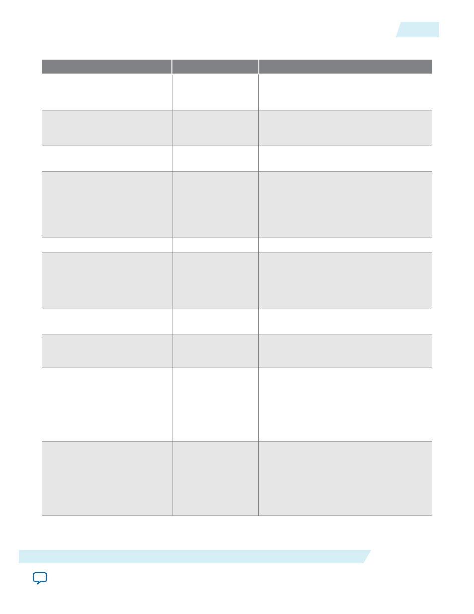
Table 8-2: Clipper II Parameter Settings
Parameter
Value
Description
Maximum input frame width
32–4096, Default =
1920
Specify the maximum frame width of the
clipping rectangle for the input field (progres‐
sive or interlaced).
Maximum input frame height
32–4096, Default =
1080
Specify the maximum height of the clipping
rectangle for the input field (progressive or
interlaced).
Bits per symbol
4–20, Default = 10
Select the number of bits per pixel (per color
plane).
Number of color planes
1–4, Default = 3
Select the number of color planes that are
sent over one data connection. The meaning
of this value depends on whether the color
planes are in parallel or serial. For example, a
value of 3 when the color planes are in serial
would mean R'G'B' R'G'B' R'G'B'.
Number of pixels in parallel
1, 2, 4
Select the number of color planes in parallel.
Color planes transmitted in
parallel
On or Off
Select whether to send the color planes in
parallel or serial. If you turn on this
parameter, and set the number of color
planes to 3, the IP core sends the R’G’B’s with
every beat of data.
Enable runtime control of
clipping parameters
On or Off
Turn on if you want to specify clipping offsets
using the Avalon-MM interface.
Clipping method
• OFFSETS
• RECTANGLE
Specify the clipping area as offsets from the
edge of the input area or as a fixed rectangle.
Left offset
0–1920, Default = 10
Specify the x coordinate for the left edge of
the clipping rectangle. 0 is the left edge of the
input area.
Note: The left and right offset values
must be less than or equal to the
input image width.
Top offset
0–1080, Default = 10
Specify the y coordinate for the top edge of
the clipping rectangle. 0 is the top edge of the
input area.
Note: The top and bottom offset values
must be less than or equal to the
input image height.
UG-VIPSUITE
2015.05.04
Video Clipping Parameter Settings
8-3
Video Clipping IP Cores
Altera Corporation